
System and method for contactless touch screen

a touch screen and touch technology, applied in the field of touch sensitive screens, can solve the problems of reducing increasing manufacturing cost, and far more expensive touch technology implementation, and achieves the effects of improving light transmission and image clarity, improving positioning reliability, and enhancing touch-based operations such as virtual keying and gesture inpu

Active Publication Date: 2012-09-25
GENERAL DISPLAY
View PDF2 Cites 60 Cited by
  • Summary
  • Abstract
  • Description
  • Claims
  • Application Information

AI Technical Summary

Benefits of technology

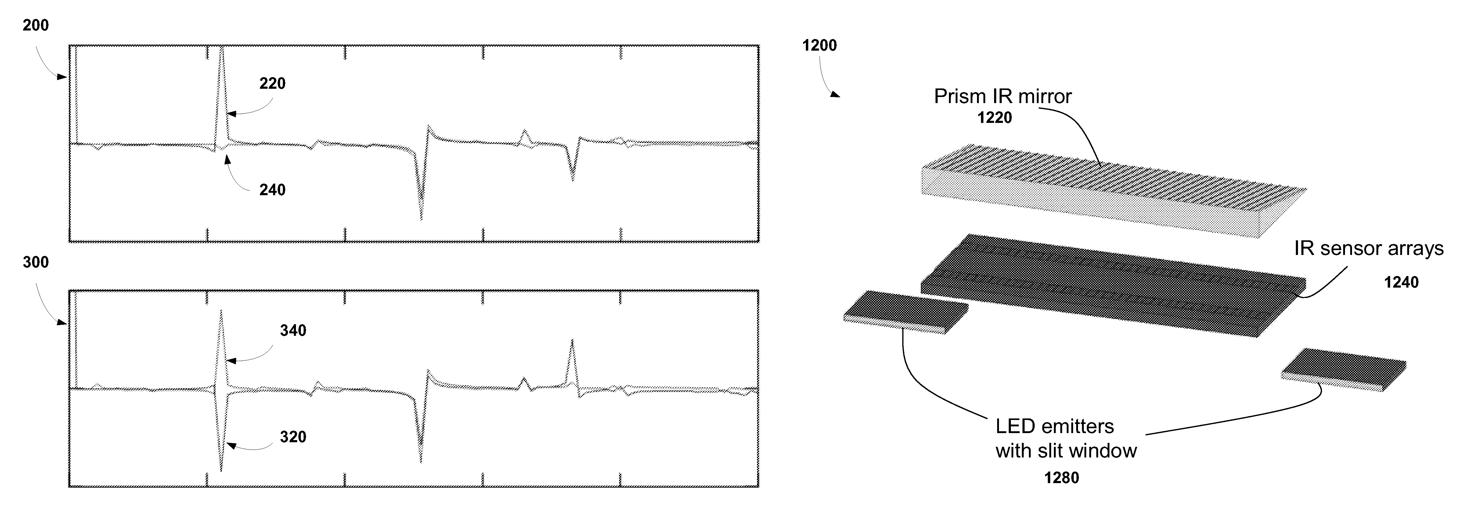
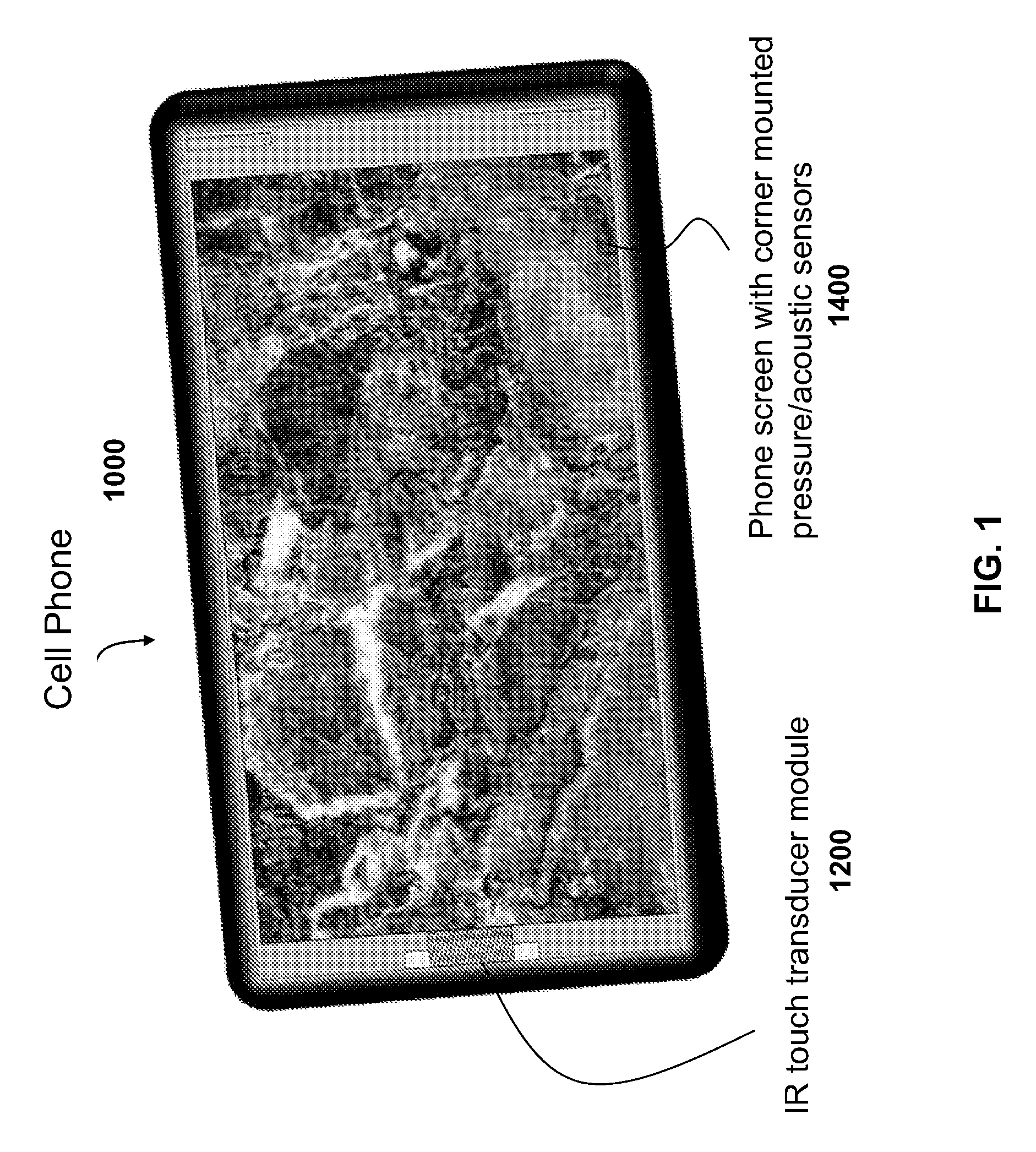
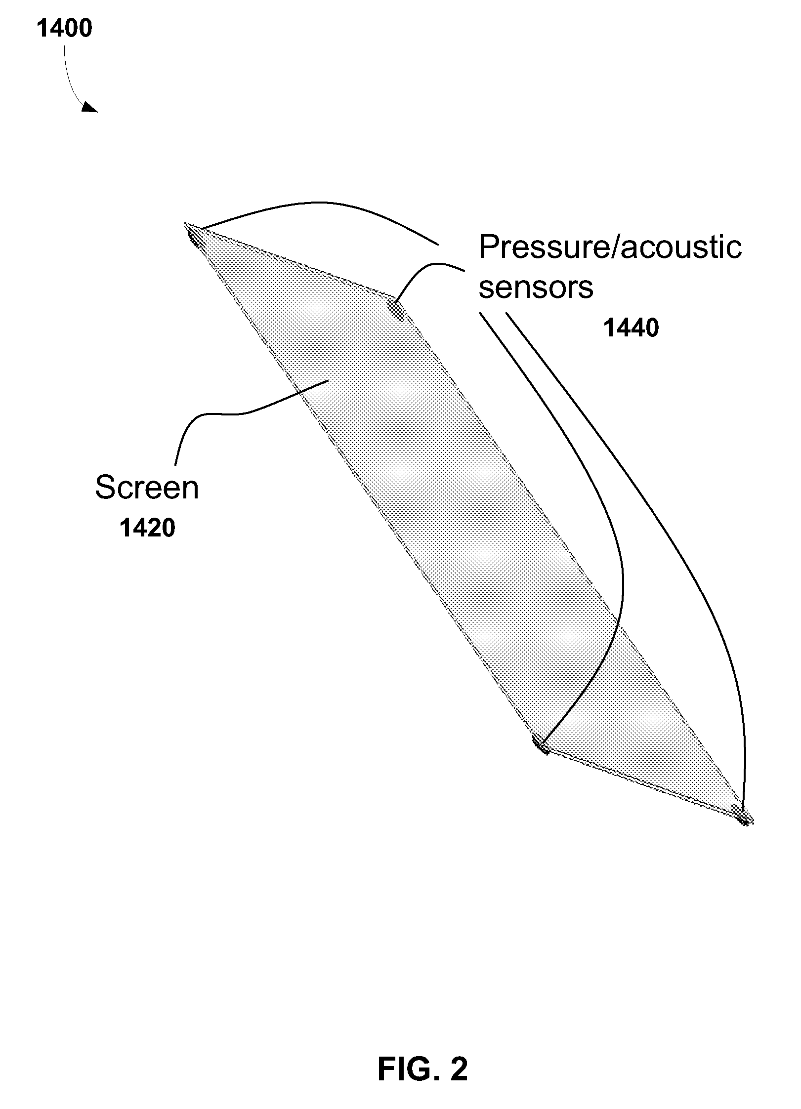
[0009]In one embodiment, the invention is a touch screen that employs a lens-less linear IR sensor array and an IR light source from a single location at the periphery of the screen to illuminate one or more objects proximate to the screen surface and detect light reflected from such objects. The sensor array is paired with a proximal grid-like barrier / reflector to create Moiré patterns on the sensor array. Digital signal processing converts such patterns into discrete Fourier transforms. The peaks of the lower order discrete Fourier spectrum as well as the complex phases of the lower order peaks can be used to determine the locations of the objects proximal to the screen accurately. A small number of pressure or surface acoustic sensors at the periphery of the screen are utilized to improve positioning reliability by providing redundant positioning information and registering physical contacts with the screen. By providing both pre-touch positioning information and actual touch locations, touch-based operations such as virtual keying and gesture input are enhanced. The absence of additional layered touch sensitive resistive or capacitive substrates improves light transmission and image clarity.

Problems solved by technology

Both resistive and capacitive touch screens require layered touch sensitive overlays on the display surface and peripheral driver / controllers to process positioning information that increase manufacturing cost and reduce light transmission and image clarity requiring a corresponding increase in the display light output to compensate.
Capacitive touch screens have more complex layered substrate structures that are harder to manufacture, thus making it a far more expensive touch technology to implement.
Gloved finger or stylus will not work on a capacitive touch screen.
Such an approach requires significant space between the cameras and the screen in order for it to operate properly, making it unsuitable for portable display devices where space is a premium.
Other approaches such as ultrasound are even more expensive to implement or are unable to be hermetically sealed to block out dust and moisture, making them generally unsuitable for mobile device applications.
Both have relatively low touch resolution in real world implementations as the cost of manufacturing goes up sharply with resolution and concomitantly the touch sensitivity drops precipitously since the sensitivity is directly proportional to the physical dimensions of the individual touch sensors.
A more serious issue with both touch technologies is the fact that the position of an object or objects can only be determined after such object make physical contact with the touch screen.
Such deficiencies make many of the gesture-based operations awkward to execute.
Unless the touch screen is large, the virtual key is usually far smaller than the finger itself, hence hitting the right key can be difficult.
This creates wear and tear on the physical screen of devices, degrading the performance of the screen with time.
It also makes it hard for the device to ascertain the intention of the user if the latter fails to maintain the physical contact continuously during the gesturing period.

Method used


Image

  • System and method for contactless touch screen
  • System and method for contactless touch screen
  • System and method for contactless touch screen

Examples


Embodiment Construction

[0019]For the purposes of this disclosure, a computer readable medium stores computer data in machine readable form. By way of example, and not limitation, a computer readable medium can comprise computer storage media and communication media. Computer storage media includes volatile and non-volatile, removable and non-removable media implemented in any method or technology for storage of information such as computer-readable instructions, data structures, program modules or other data. Computer storage media includes, but is not limited to, RAM, ROM, EPROM, EEPROM, flash memory or other solid-state memory technology, CD-ROM, DVD, or other optical storage, magnetic cassettes, magnetic tape, magnetic disk storage or other mass storage devices, or any other medium which can be used to store the desired information and which can be accessed by the computer.

[0020]For the purposes of this disclosure a module is a software, hardware, or firmware (or combinations thereof) system, process o...


PUM


Abstract

A touch screen that employs a lens-less linear IR sensor array and an IR light source from a single location at the periphery of the screen to illuminate one or more objects proximate to the screen surface and detect light reflected from such objects. The sensor array is paired with a proximal grid-like barrier / reflector to create Moiré patterns on the sensor array. Digital signal processing converts such patterns into discrete Fourier transforms. The peaks of the lower order discrete Fourier spectrum as well as the complex phases of the lower order peaks can be used to determine the locations of the objects proximal to the screen accurately. A small number of pressure or surface acoustic sensors at the periphery of the screen are utilized to improve positioning reliability by providing redundant positioning information and registering physical contacts with the screen.

Description

[0001]This application includes material which is subject to copyright protection. The copyright owner has no objection to the facsimile reproduction by anyone of the patent disclosure, as it appears in the Patent and Trademark Office files or records, but otherwise reserves all copyright rights whatsoever.FIELD OF THE INVENTION[0002]The present invention relates to touch sensitive screens and, more particularly, to IR based proximal object illumination sensing and position determination.BACKGROUND OF THE INVENTION[0003]Touch screen technologies can be broadly classified into six main categories: resistive, capacitive, peripheral IR, ultrasound, optical imaging, and surface acoustic / pressure. Among those, only resistive, capacitive and optical imaging technologies can readily support multi-touch touch screen capabilities. Although resistive touch screen technology has been the most commonly used technology for small interactive displays due to its relatively low cost, capacitive tou...

Claims


Application Information

Patent Timeline
Patent Type & Authority Patents(United States)
IPC IPC(8): G06F3/042
CPCG06F3/0304G06F3/043G06F3/042G06F3/0412
Inventor LEE, YEE CHUN
Owner GENERAL DISPLAY
Learn More