Cartridge with developer layer thickness regulating member and image forming apparatus including the same

a technology of developer layer and thickness regulation, applied in the direction of electrographic process apparatus, instruments, optics, etc., can solve the problems of cost reduction, and achieve the effects of reducing cost, space saving, and simplifying constitution

Active Publication Date: 2012-09-25
CANON KK
View PDF48 Cites 33 Cited by
  • Summary
  • Abstract
  • Description
  • Claims
  • Application Information

AI Technical Summary

Benefits of technology

[0007]A principal object of the present invention is to simplify a constitution for electrically connecting a main assembly of an electrophotographic image forming apparatus to a cartridge by reducing the number of parts so as to realize cost reduction and space saving.

Problems solved by technology

However, in recent years, the developing cartridge has been required to realize further simplification, further cost reduction, and further space saving.

Method used


Image

  • Cartridge with developer layer thickness regulating member and image forming apparatus including the same
  • Cartridge with developer layer thickness regulating member and image forming apparatus including the same
  • Cartridge with developer layer thickness regulating member and image forming apparatus including the same

Examples


first embodiment

(General Structure of Electrophotographic Image Forming Apparatus)

[0035]First, with reference to FIGS. 1 and 2, a general structure and an image forming operation of the electrophotographic image forming apparatus will be described.

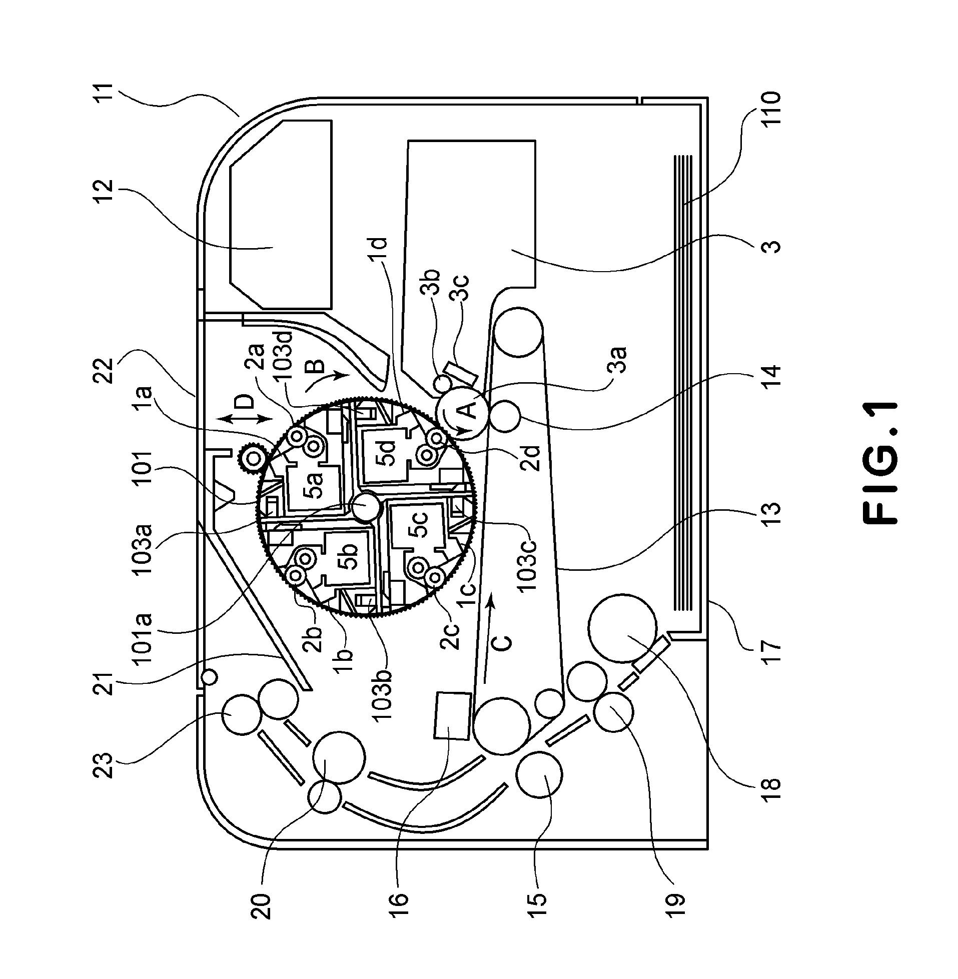
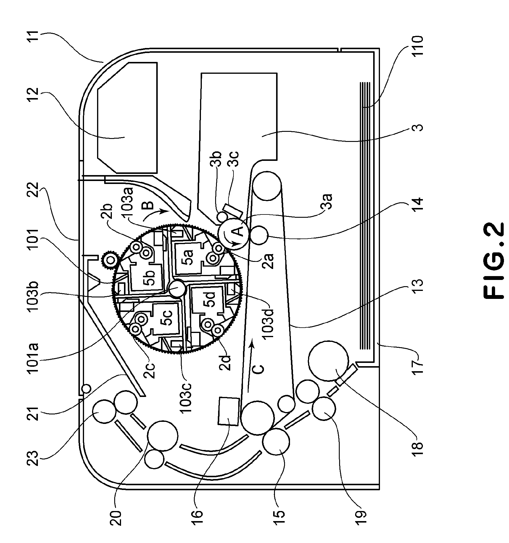
[0036]FIG. 1 and FIG. 2 are sectional views each showing an image forming apparatus main assembly 11 of the image forming apparatus and a developing cartridge 5.

[0037]The image forming apparatus shown in each of FIG. 1 and FIG. 2 is a four color-based full-color laser beam printer to which four developing cartridges 5 and a single drum cartridge 3 are detachably mountable. In a state in which the drum cartridge 3 and the developing cartridges 5 are mounted in the main assembly 11, an exposure means (a laser scanner unit) 12 is disposed above the drum cartridge 3. Further, below the cartridges 3 and 5, a sheet feeding cassette 17 accommodating the recording material (hereinafter referred to as a sheet) 110 is disposed. In the main assembly 11, along a conv...

second embodiment

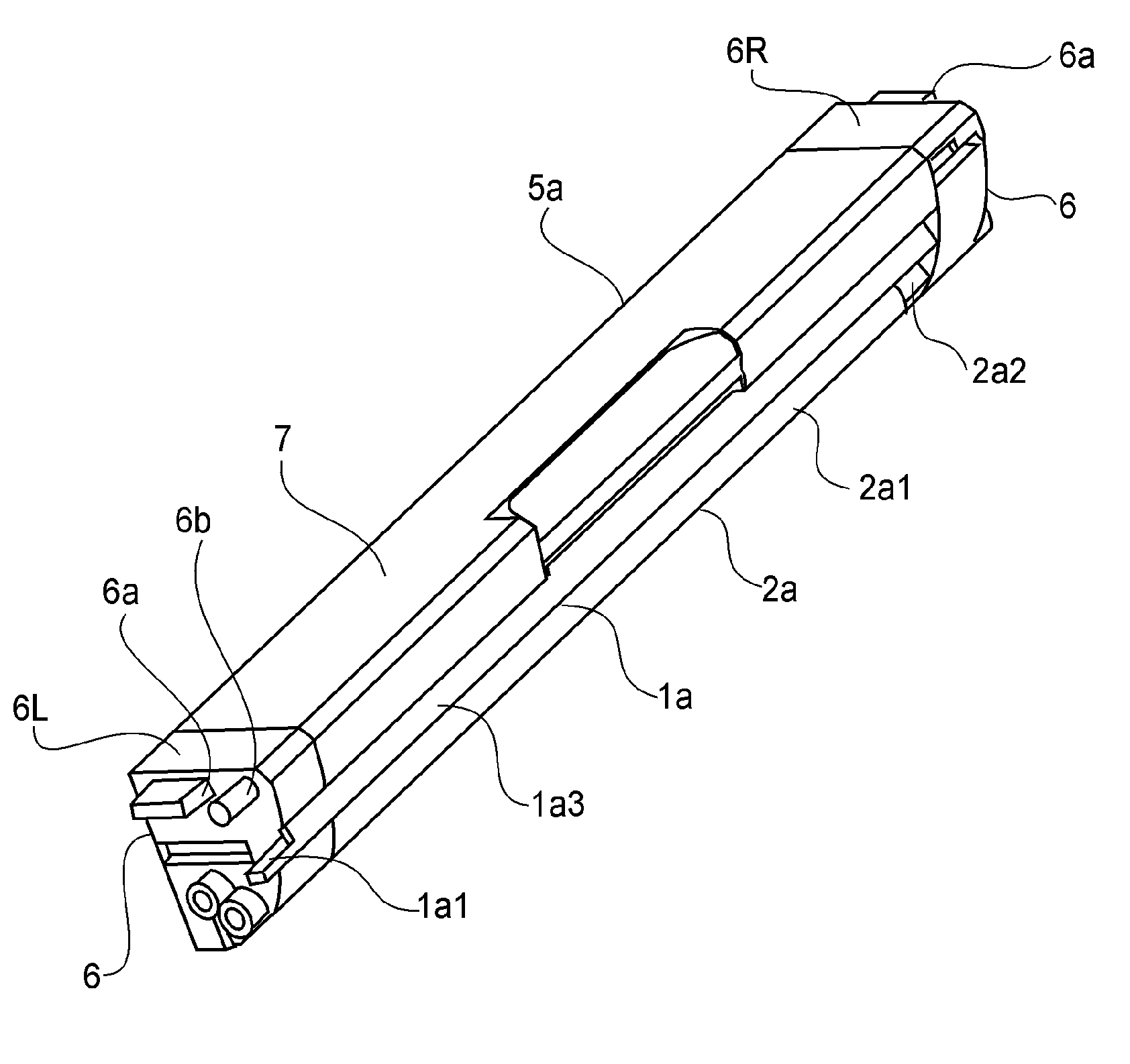
[0077]FIG. 11(b) and FIG. 12(b) illustrate Second Embodiment. In this embodiment, a part of the side member 6 is different from that in First Embodiment. That is, an end portion (a part) of the developing blade 1 with respect to the longitudinal direction of the developing blade 1 is covered with a covering portion 6c. More specifically, the covering portion 6c covers the rear surface of the contact surface 1a1 and rear surface edge portions of the contact surface 1a1 but exposes the front surface of the contact surface 1a1 toward the main assembly electrical contact 102a. As a result, it is possible to further effectively prevent the contact surface 1a1 from being touched by the user.

[0078]In the above-described embodiments, the developing cartridge 5 including the developing roller and the developing blade is described as the example of the cartridge detachably mountable to the image forming apparatus main assembly but the cartridge in the present invention is not limited thereto....


PUM


Abstract

A cartridge detachably mountable to a main assembly of an electrophotographic image forming apparatus includes a developer carrying member for developing an electrostatic latent image formed on an image bearing member, and an electroconductive developer layer thickness regulating member for regulating a layer thickness of a developer deposited on the developer carrying member. A part of the developer layer thickness regulating member is directly contactable to the main assembly electrical contact.

Description

FIELD OF THE INVENTION AND RELATED ART[0001]The present invention relates to a cartridge and an electrophotographic image forming apparatus to which the cartridge is detachably mountable.[0002]In a conventional electrophotographic image forming apparatus, an electrostatic latent image formed on an electrophotographic portion is developed by a developing means including a developing roller and a developing blade to be visualized as a toner image. In such an image forming apparatus, a constitution in which the developing means including the developing roller and the developing blade is prepared by integrally supporting the roller and the blade into a cartridge and the resultant developing cartridge is detachably mountable to a main assembly of the image forming apparatus has been known.[0003]In order to develop the electrostatic latent image formed on the photosensitive drum by depositing toner on the electrostatic latent image, it is necessary to apply a bias voltage to the developin...

Claims


Application Information

Patent Timeline
Patent Type & Authority Patents(United States)
IPC IPC(8): G03G15/00G03G15/08
CPCG03G15/0812G03G21/1867
Inventor UNEME, TETSUSHIUENO, TAKAHITONAKAMURA, YUUKI
Owner CANON KK
Why Eureka
Try Eureka