Sintered compact of composite oxide, amorphous film of composite oxide, process for producing said film, crystalline film of composite oxide and process for producing said film

a composite oxide and compact technology, applied in the direction of conductive materials, cable/conductor manufacturing, insulating support, etc., can solve the problems of particle generation, adverse effect of particles on the flatness and crystallinity of sputtered film, and inability to obtain amorphous film by sputtering upon adding water, etc., to achieve fast etching rate, low film resistivity, and superior

Active Publication Date: 2012-10-02
JX NIPPON MINING & METALS CORP
View PDF23 Cites 5 Cited by
  • Summary
  • Abstract
  • Description
  • Claims
  • Application Information

AI Technical Summary

Benefits of technology

[0018]Thus, an object of the present invention is to provide an ITO thin film, its production method, and a sintered compact for producing such a film for use as a display electrode or the like in a flat panel display which can be made into an amorphous ITO film by way of sputter deposition without heating the substrate or adding water during deposition. With this sputtered film, a part of the crystallized film will not remain as residue during the etching process, and superior etching properties are yielded by etching at a relatively fast etching rate and the like. In addition, this sputtered film can be crystallized by annealing at a temperature that is not too high, and the resistivity after crystallization is sufficiently low.
[0019]As a result of intense study regarding an oxide target obtained by adding various elements to ITO, the present inventors discovered that the foregoing problems can be overcome by sputtering a sintered compact obtained by adding an adequate concentration of calcium or calcium and magnesium to ITO under prescribed conditions, and annealing the obtained sputtered film under prescribed conditions, and thereby achieved the present invention.

Problems solved by technology

If a part of the ITO film becomes crystallized as described above, such crystallized portion will remain as so-called etching residue in the subsequent etching process, and cause problems such as a short circuit, since the etching rate of that part will be lower than that of an amorphous portion by roughly two orders of magnitude
Nevertheless, the method of attempting to obtain an amorphous film by sputtering upon adding water entails numerous problems.
These particles have an adverse effect on the flatness and crystallinity of the sputtered film.
Since particles will not be generated if water is not added, the problem of generation of particles is caused by adding water.
On the other hand, however, if the concentration of the water to be added is increased in order to reliably obtain an amorphous sputtered film, the crystallization temperature upon crystallizing the film in the subsequent annealing process will become extremely high, which is a problem in that the resistivity of the obtained film will become extremely high.
In other words, if sputtering is performed upon adding water to amorphize the entire sputtered film, it is necessary to constantly monitor and control the water concentration within the chamber, however, this is extremely difficult and requires considerable time and effort.
Thus, it is not possible to attain the advantages in the production process of crystallizing the film and incomparably reducing the etching rate, and the resistivity of the sputtered film will be approximately 0.45 mΩcm, which is higher than the crystallized ITO film.
Moreover, the visible light average transmission factor of this film is roughly 85%, and is inferior to an ITO film.
As described above, the conventional technology which uses a sintered compact having a composition of adding zinc to indium oxide as the target is insufficient as a solution since it has drawbacks such as the film resistivity being high.

Method used


Image

  • Sintered compact of composite oxide, amorphous film of composite oxide, process for producing said film, crystalline film of composite oxide and process for producing said film
  • Sintered compact of composite oxide, amorphous film of composite oxide, process for producing said film, crystalline film of composite oxide and process for producing said film
  • Sintered compact of composite oxide, amorphous film of composite oxide, process for producing said film, crystalline film of composite oxide and process for producing said film

Examples


example 1

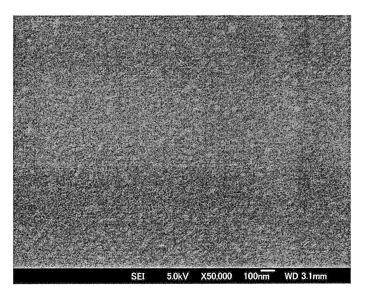
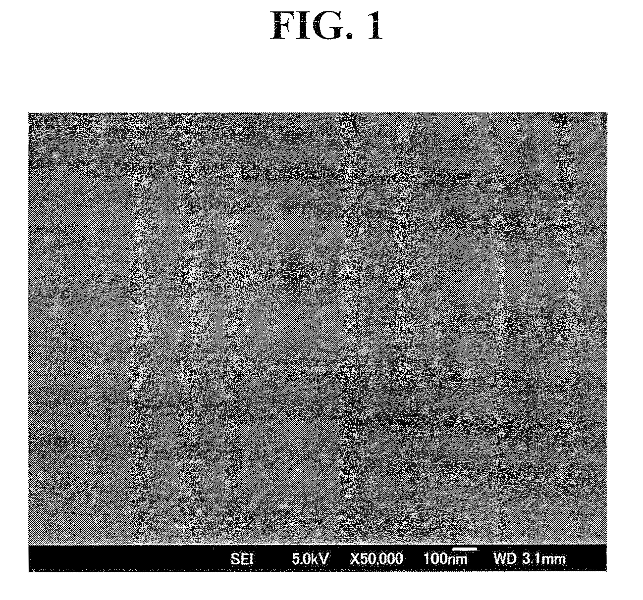
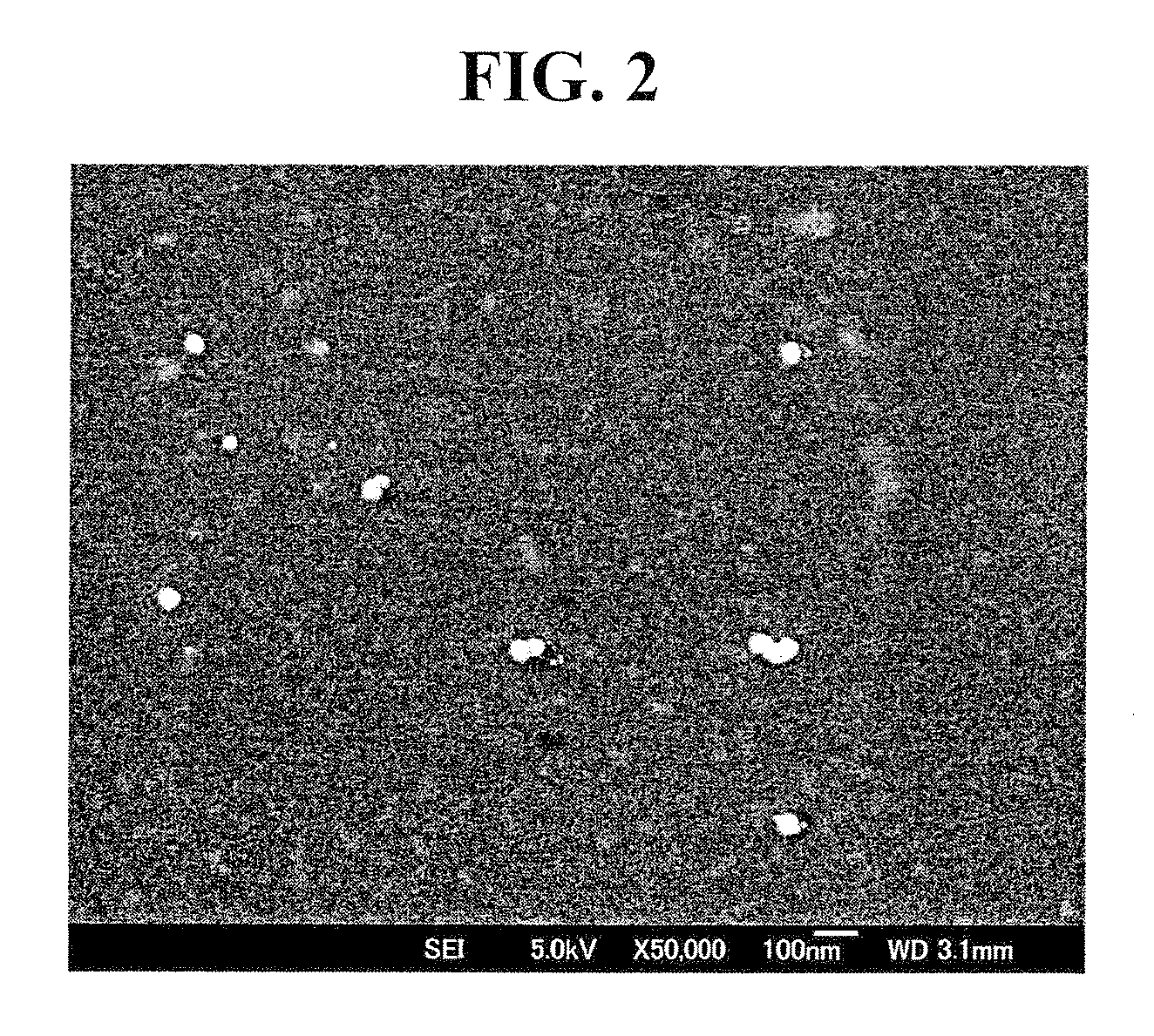
[0088]Indium oxide powder, tin oxide powder and calcium oxide powder as the raw materials were weighed to achieve In:Sn:Ca=90.78:9.08:0.14% based on the atomicity ratio, and mixed with a super mixer in an atmospheric environment for 3 minutes at 3000 rotations per minute.

[0089]Subsequently, water was added to the mixed powder to obtain slurry in which the solid content is 50%, and the slurry was pulverized with zirconia beads having a diameter of 1 mm for 2 hours to achieve an average grain size (D50) of the mixed powder of 0.6 μm or less. PVA (polyvinyl alcohol) was thereafter mixed at a ratio of 125 cc per kilogram of slurry, and granulated under the conditions where the granulator's inlet temperature was 220° C., outlet temperature was 120° C., and disk rotation was 9000 rpm.

[0090]Subsequently, granulated powder was filled in a mold of a prescribed size to obtain a target having an 8-inch diameter, and pressed at a surface pressure of 780 kgf / cm2 to obtain a compact. The compact ...

examples 2 to 6

[0100]The sintered compact composition of Example 1 was changed as follows in Examples 2 to 6, whereby the other conditions are the same as Example 1.

[0101]The atomicity ratio % of the sintered compact composition in Example 2, 3, 4, 5 and 6 was changed to In:Sn:Ca=90.66:9.07:0.27, In:Sn:Ca=90.41:9.04:0.55, In:Sn:Ca=89.91:8.99:1.10, In:Sn:Ca=89.41:8.94:1.65, and In:Sn:Ca=89.09:8.91:2.00 respectively.

[0102]As a result of measuring the resistivity of the sputtering targets obtained as described above, the resistivity was in the range of 0.15 to 0.18 mΩcm. The crystallinity during deposition, the crystallization temperature, and the resistivity of the crystallized film were shown in Table 1, respectively.

[0103]From the foregoing results, the crystallinity of the deposited film was amorphous in all of the Examples, and, although the crystallization temperature gradually increases to a higher temperature pursuant to the increase in the calcium additive concentration, as evident from the ...

examples 7 to 14

[0105]In substitute for adding calcium as in Examples 1 to 6, calcium and magnesium were added in Examples 7 to 14.

[0106]Here, the calcium concentration and the total of calcium and magnesium were made to coincide. Specifically, the calcium concentration of Example 1 and the total concentration of calcium and magnesium in Example 7 were made to be the same. Moreover, the calcium concentration of Example 2 and the total concentration of calcium and magnesium in Examples 8, 9, and 10 were made to be the same, respectively, and the concentration of calcium and magnesium in Examples 8, 9, and 10 was changed to 1:1, 1:2, and 2:1, respectively.

[0107]In addition, the calcium concentration and the total concentration of calcium and magnesium of Example 3 and Example 11, Example 4 and Example 12, Example 5 and Example 13, and Example 6 and Example 14 were made to be the same. Upon measuring the resistivity of the sputtering targets obtained as described above, the resistivity was in the rang...


PUM

PropertyMeasurementUnit
temperatureaaaaaaaaaa
crystallization temperatureaaaaaaaaaa
temperatureaaaaaaaaaa

Abstract

Provided is an amorphous film substantially comprised of indium, tin, calcium and oxygen, wherein tin is contained at a ratio of 5 to 15% based on an atomicity ratio of Sn / (In+Sn+Ca) and calcium is contained at a ratio of 0.1 to 2.0% based on an atomicity ratio of Ca / (In+Sn+Ca), and remnant is indium and oxygen. The film can be further crystallized by annealing at a temperature of 260° C. or lower in which resistivity of the film will be 0.4 mΩcm or less. An ITO thin film for use as a display electrode or the like in a flat panel display can be made into an amorphous ITO film by way of sputter deposition without heating the substrate or adding water during deposition. This ITO film is characterized in that it will crystallize by annealing at a temperature of 260° C. or less, which is not such a high temperature, and have low resistivity after being crystallized. Thus, the present invention aims to provide a method of producing such a film and a sintered compact for producing such a film.

Description

BACKGROUND OF THE INVENTION[0001]The present invention relates to a crystalline film of composite oxide and its production method and an amorphous film of composite oxide and its production method which are to be used as an electrode in a flat panel display or the like, as well as to a sintered compact of composite oxide to be used in producing the foregoing oxide films.[0002]An ITO (Indium Tin Oxide) film is characterized in low resistivity and high transmission factor, and can be microfabricated easily. Since these characteristics are superior in comparison to other transparent conductive films, an ITO film is being broadly used in various fields including for use as a display electrode in a flat panel display. The deposition method of the ITO film in today's industrial production process is mostly based on the so-called sputter deposition method of performing sputtering using an ITO sintered compact as the target since the ITO film can be uniformly formed on a large area with fav...

Claims


Application Information

Patent Timeline
Patent Type & Authority Patents(United States)
IPC IPC(8): H01B1/08B05D5/12
CPCC04B35/457C23C14/086C23C14/5806C04B35/01C04B35/6262C04B35/6263C04B35/62675C04B35/63416C04B35/62695C04B2235/3293C04B2235/3206C04B2235/3208C04B2235/3286C04B2235/5445C04B2235/6562C04B2235/72C04B2235/77C04B35/00H01B5/14C23C14/08H01B13/00
Inventor IKISAWA, MASAKATSUYAHAGI, MASATAKAOSADA, KOZOKAKENO, TAKASHI
Owner JX NIPPON MINING & METALS CORP
Why Eureka
Try Eureka