Active rectifier and method for energy harvesting power management circuit

a technology of active rectifiers and power management circuits, applied in the field of low power rectifiers, can solve the problems of large voltage drop, increase the amount of current consumed, and inability to meet the requirements of low-voltage signals, and achieve the effect of low-power active rectifiers and efficient rectifying very low-power signals

Active Publication Date: 2012-10-09
TEXAS INSTR INC
View PDF3 Cites 26 Cited by
  • Summary
  • Abstract
  • Description
  • Claims
  • Application Information

AI Technical Summary

Benefits of technology

[0012]It is an object of the invention to provide a very low power active rectifier circuit and method capable of efficiently rectifying very low power signals.
[0013]It is another object of the invention to provide a very low power active rectifier circuit and method capable of efficiently rectifying very low power signals having voltage levels of less than approximately 400 millivolts.
[0014]It is another object of the invention to provide a very low power active rectifier circuit and method capable of efficiently rectifying very low power signals having voltage levels of less than approximately 400 millivolts and requiring a current consumption of only a few nanoamperes.

Problems solved by technology

This large voltage drop greatly decreases the efficiency of conventional rectifier 1 for applications with low input voltage sources.
The large voltage drop also makes passive rectifier 1 impractical for rectifying low voltage signals under about 400 millivolts, for example low voltage signals generated by energy harvesting devices such as thermopiles, solar cells, and inductive vibration sensors.
That increases the amount of current consumed by the comparators because their speed is approximately proportional to their consumption of current and therefore results in high current and power consumption of active rectifier 5.
This means comparators 7 and 8 of FIG. 2 must be relatively large, complex, high power circuits, the size, complexity, and power requirements of which increase even further if the active rectifiers must be able to rectify both large input voltages (above about 1 to 2 volts) and small input voltages (below about 20 to 100 millivolts).
Consequently, the active rectifier of FIG. 2 necessarily consumes far too much power to be practical for use in rectifying very low power signals.

Method used


Image

  • Active rectifier and method for energy harvesting power management circuit
  • Active rectifier and method for energy harvesting power management circuit
  • Active rectifier and method for energy harvesting power management circuit

Examples


Embodiment Construction

[0031]When energy is to be micro-harvested or scavenged from very low voltage, low-frequency power signal sources such as ambient solar, vibrational, or thermal power sources, it is highly desirable to be able to rectify the low voltage, low-frequency signals much more efficiently than has been achievable in the prior art.

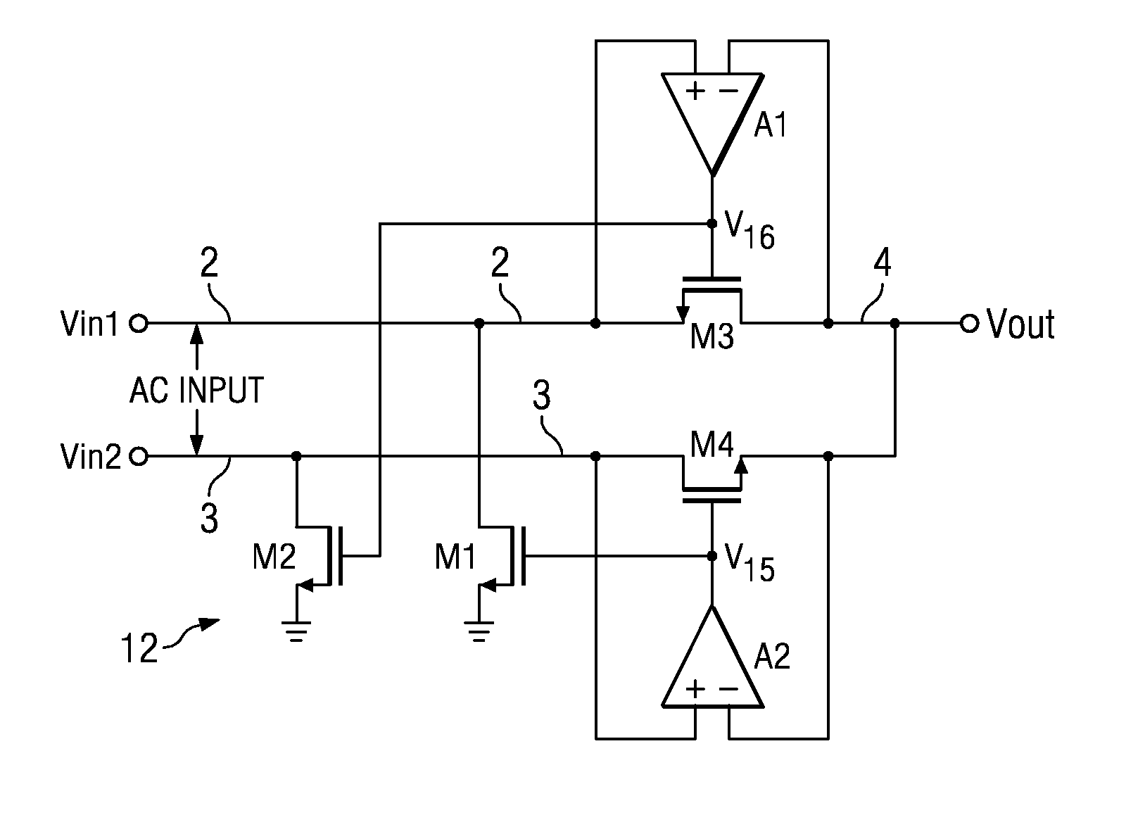
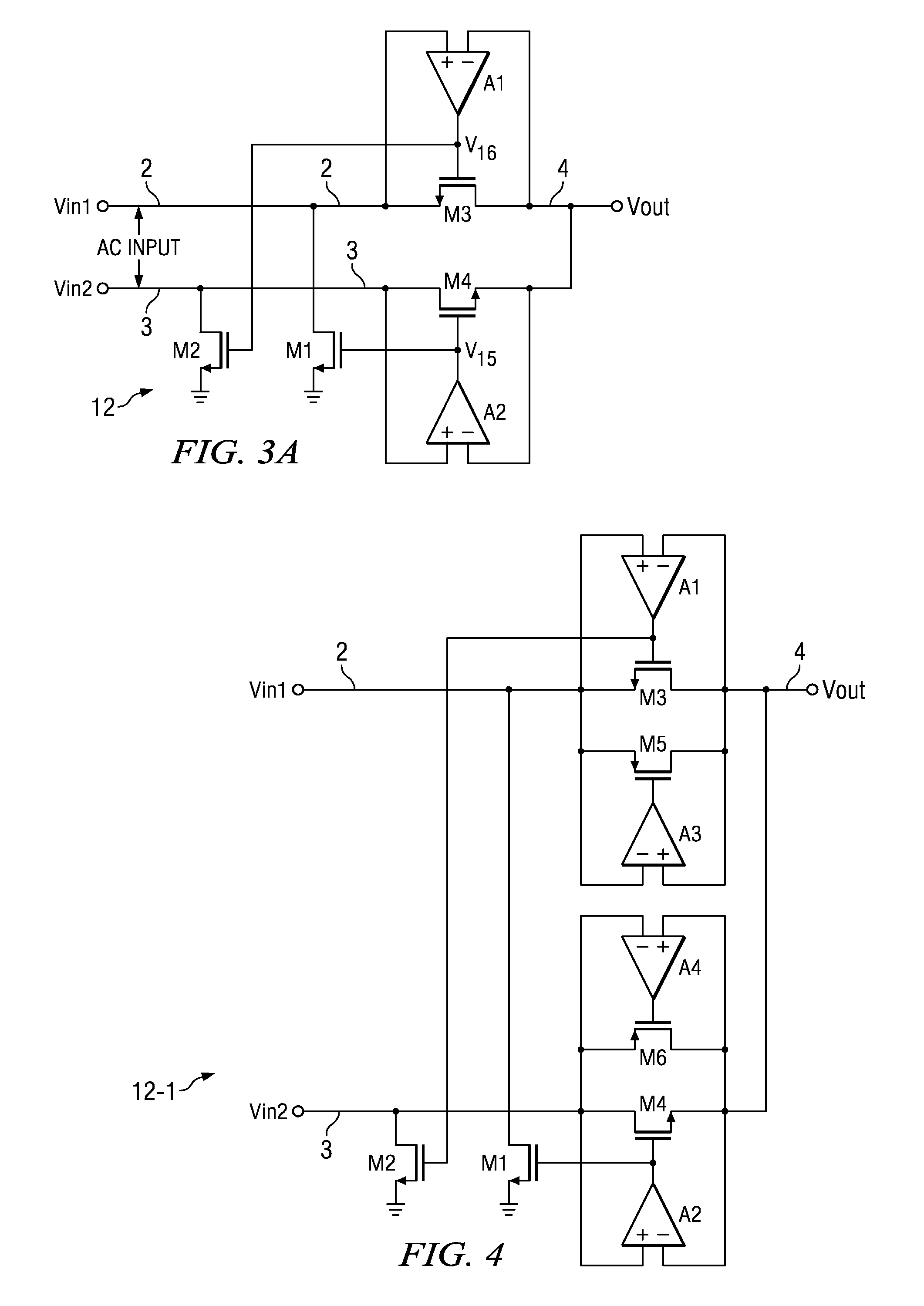
[0032]To this end, FIG. 3A shows a generalized diagram of a full wave active rectifier 12 which can be implemented in standard CMOS technology as shown in subsequently described FIG. 3B. Rectifier 12 includes a N-channel switching transistor M3 having a source (or drain) connected to conductor 2 on which an input voltage Vin1 is received, and also includes a N-channel switching transistor M4 having a drain (or source) connected to conductor 3 on which an input voltage Vin2 is received. A harvested AC input signal Vin1-Vin2 can be applied between conductors 2 and 3. The input signals Vin1 and Vin2 can come, for example, from a piezo harvester or an induction harvest...


PUM


Abstract

An active rectifier (12) couples a first input voltage (Vin1) to a first electrode of a first transistor (M3) having a second electrode coupled to an output (4) conducting an output voltage (Vout), and couples a second input voltage (Vin2) to a first electrode of a second transistor (M4) having a second electrode coupled to the output conductor. A first amplifier (A1) controls a voltage (V16) of a gate of the first transistor to maintain an input offset of the first amplifier between the first input voltage and the output voltage while the first input voltage exceeds the output voltage, and a second amplifier (A2) controls a voltage (V15) on a gate of the second transistor to maintain an input offset between the second input voltage and the output voltage while the first input voltage exceeds the output voltage. The input offsets prevent backflow of current from the output to either of the first electrodes when the first or second input is nearly equal to the output voltage.

Description

BACKGROUND OF THE INVENTION[0001]The present invention relates generally to low power rectifiers, especially to rectifiers suitable for “micro-harvesting” very low levels of low voltage, low frequency AC power. The invention relates more particularly to active rectifiers that can effectively rectify harvested low voltage AC power by reducing voltage drop and power loss across switches of the active rectifier circuits.[0002]Engineers have attempted to design very low power integrated circuits, for example integrated circuits that require extremely low amounts of operating current and which can be operated without being plugged into conventional AC power systems. Instead, it is desirable that such ultra-low-power integrated circuits be powered by small amounts of power “scavenged” from ambient solar, vibrational, thermal, and / or biological energy sources by means of micro-energy harvesting devices and stored in batteries or super-capacitors (since such ambient power sources often are ...

Claims


Application Information

Patent Timeline
Patent Type & Authority Patents(United States)
IPC IPC(8): H02M7/217
CPCH02M7/219H02M2007/2195Y02B70/1408H03K2017/307Y02B70/10H02M7/2195
Inventor IVANOV, VADIM V.
Owner TEXAS INSTR INC
Why Eureka
Try Eureka