Check patentability & draft patents in minutes with Patsnap Eureka AI!

Optical fiber sensor

a technology of optical fiber and optical fiber, applied in the field of optical fiber sensors, can solve the problems of deterioration in cold startability and driving performance, increased toxic components in exhaust fumes, and expensive measurement devices such as light spectrum analyzers or the like, and achieves the effect of simple construction and high sensitivity

Inactive Publication Date: 2012-10-09
MITSUBISHI ELECTRIC CORP
View PDF9 Cites 8 Cited by
  • Summary
  • Abstract
  • Description
  • Claims
  • Application Information

AI Technical Summary

Benefits of technology

The sensor achieves high sensitivity in detecting refractive indices across a wide range, enabling accurate identification of gasoline types and alcohol content, thereby improving engine performance and reducing emissions with a cost-effective setup.

Problems solved by technology

Further, in this engine, there arises deterioration in cold startability and deterioration in driving performance, such as a breathing phenomenon and the like, and there causes an increase of toxic components in exhaust fumes due to incomplete combustion.
In the detection using the short-period tilted-grating, as disclosed in Patent Document 1, since it is necessary to measure the spectra shape of cladding propagation mode loss peak with high resolution of wavelength, an expensive measurement device such as a light spectrum analyzer or the like is needed.
As a result, Patent Document 1 has a problem of impairing the effect of enlarging the measurable range of refractive index.
Patent Document 2, however, has a problem that the measurable range of refractive index can not be sufficiently enlarged.

Method used


Image

  • Optical fiber sensor
  • Optical fiber sensor
  • Optical fiber sensor

Examples


Embodiment Construction

The First Preferred Embodiment

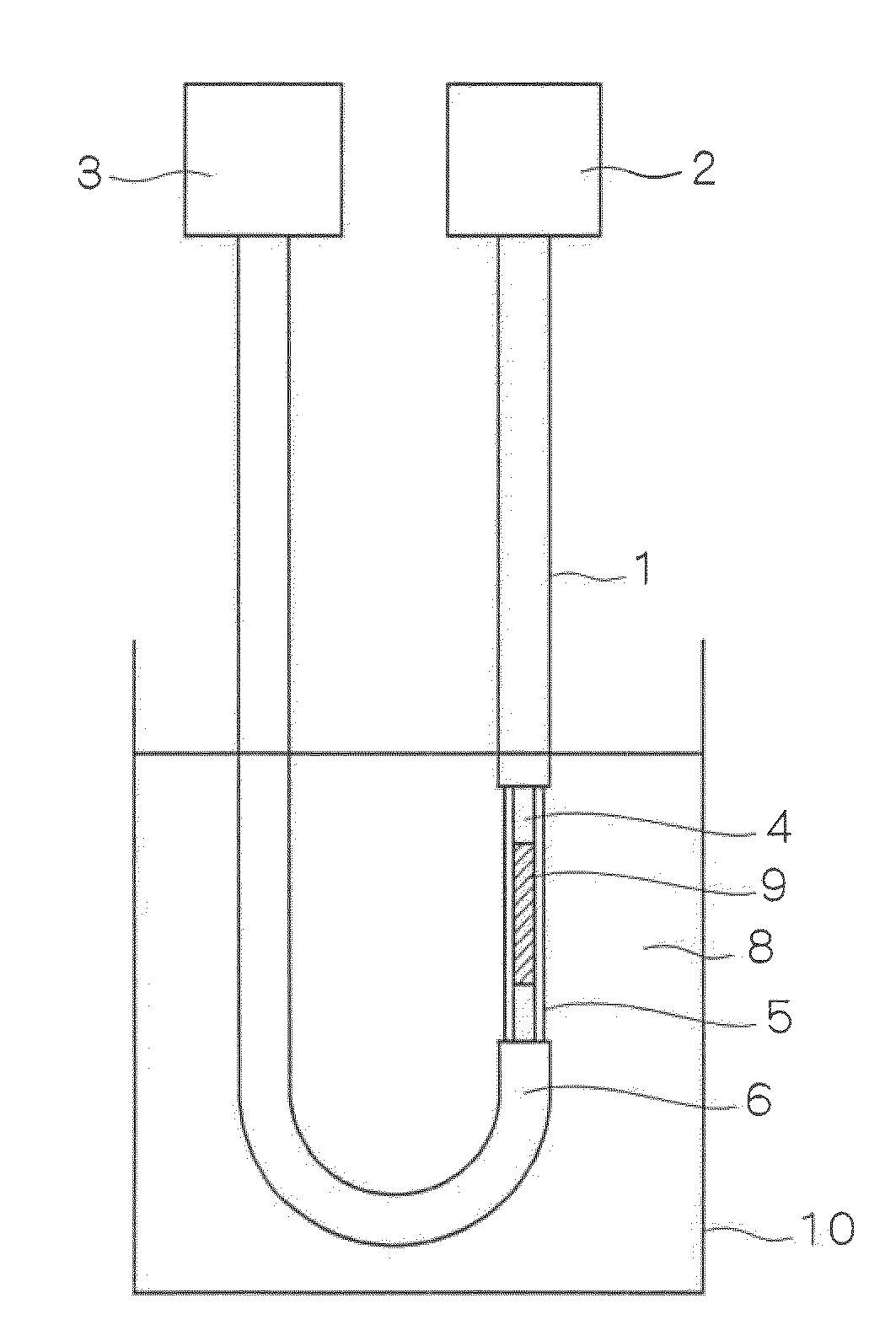
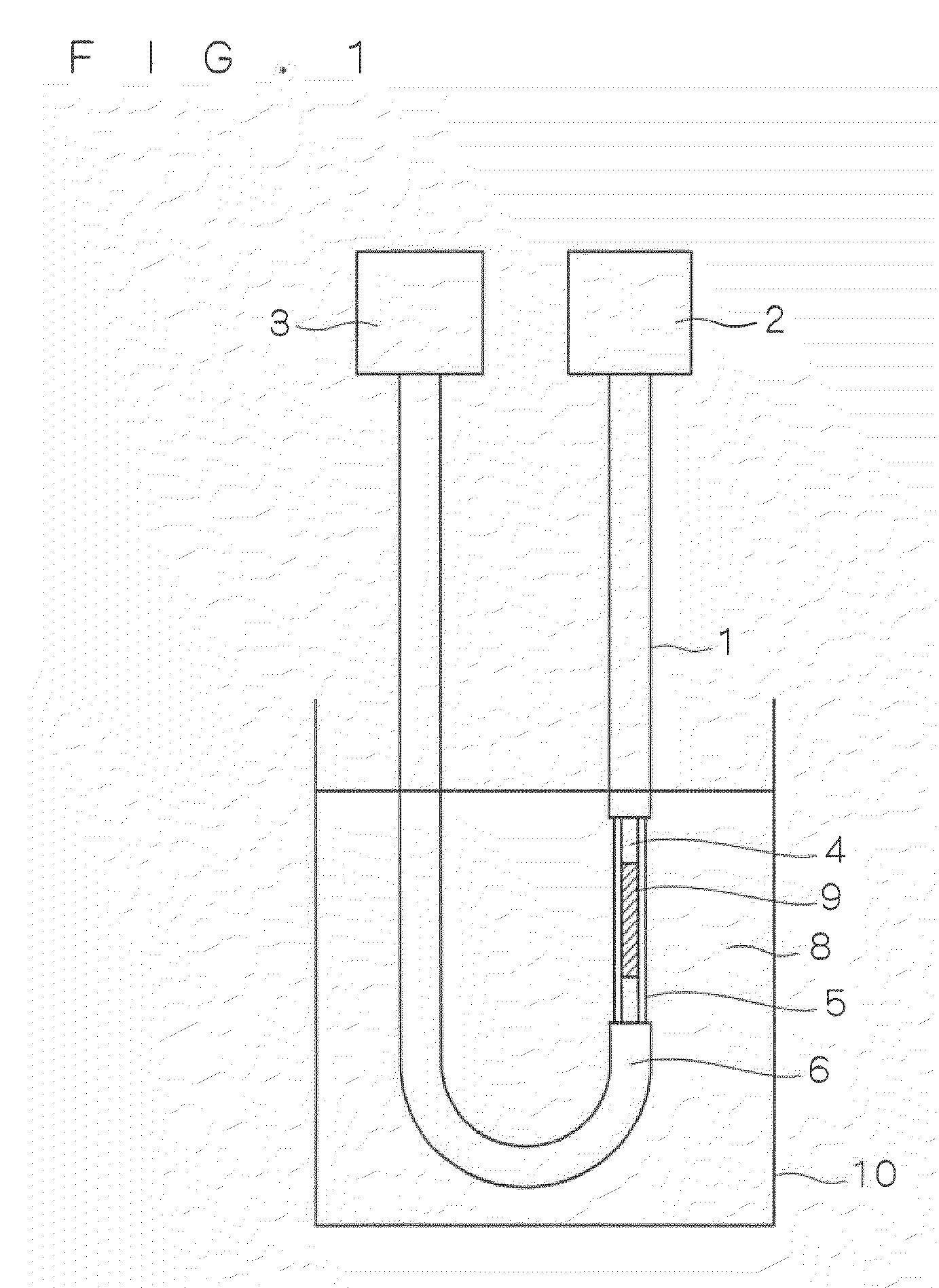
[0045]FIG. 1 is a schematic diagram showing an optical fiber sensor in accordance with the first preferred embodiment of the present invention. The optical fiber sensor shown in FIG. 1 is a sensor capable of detecting a refractive index of liquid. In the optical fiber sensor of FIG. 1, at an end of an optical fiber 1, a light source 2 is arranged and at the other end thereof, a light receiving part 3 is arranged. The optical fiber 1 comprises a core 4 propagating light emitted from the light source 2, a cladding 5 which is so provided as to cover the core 4 so that the light may be enclosed in the core 4 and a fiber jacket 6 covering and protecting these parts.

[0046]Further, in the optical fiber 1, for measurement of refractive index of liquid, part of the fiber jacket 6 is removed so that a liquid 8 which is a medium to be measured may come into direct contact with the cladding 5. Furthermore, in the optical fiber 1 of FIG. 1, a Bragg grating (hereinaf...


PUM


Abstract

An optical fiber sensor measuring refractive index of a medium with high sensitivity in a wide range. The optical fiber sensor includes an optical fiber causing a transmission loss due to leakage in the clad propagation mode from a portion of a core and a clad where a Bragg grating is provided, a light source permitting light in a wavelength band in the clad propagation mode to enter the optical fiber, and a light-receiving section receiving the transmitted or reflected light transmitted through the core and the clad at the portion where the Bragg grating is provided. The refractive index of the medium to be measured in contact with the clad is measured according to total intensity of the light received by the light-receiving section. The Bragg grating is inclined at a predetermined angle of inclination to the vertical line vertical to the length direction of the optical fiber.

Description

TECHNICAL FIELD[0001]The present invention relates to an optical fiber sensor, and more particularly to an optical fiber sensor capable of detecting liquid properties by utilizing a refractive index.BACKGROUND ART[0002]Pure gasoline used as fuel for motorcar engines includes light gasoline whose main ingredient is a hydrocarbon such as heptane, pentane and the like, heavy gasoline whose main ingredient is a hydrocarbon such as benzene and the like and medium gasoline (normal regular gasoline) which is a medium type of these two. If the heavy gasoline is used as fuel for an engine whose ignition timing and the like are controlled to be matched to the light gasoline, for example, ignition of the engine is delayed. Further, in this engine, there arises deterioration in cold startability and deterioration in driving performance, such as a breathing phenomenon and the like, and there causes an increase of toxic components in exhaust fumes due to incomplete combustion.[0003]In the United ...

Claims


Application Information

Patent Timeline
Patent Type & Authority Patents(United States)
IPC IPC(8): G02B6/00G02B6/34
CPCG01N21/774
Inventor NISHIKAWA, SATOSHITAKABAYASHI, MASAKAZUYOSHIARA, KIICHIYAGYU, EIJIMITANI, TATEKIHAMATANI, YUTARO
Owner MITSUBISHI ELECTRIC CORP
Features
  • R&D
  • Intellectual Property
  • Life Sciences
  • Materials
  • Tech Scout
  • Unparalleled Data Quality
  • Higher Quality Content
  • 60% Fewer Hallucinations
Learn More