One turn actuated duration dual mechanism spray dispenser pump

a dual-mechanics, spray dispenser technology, applied in the field of spray dispensers, can solve the problems of unfavorable conventional non-chemical mechanical spray dispensers, restrictions, and increased scrutiny of aerosol dispensers that use chemical propellants

Active Publication Date: 2012-10-16
ALTERNATIVE PACKAGING SOLUTIONS
View PDF18 Cites 24 Cited by
  • Summary
  • Abstract
  • Description
  • Claims
  • Application Information

AI Technical Summary

Benefits of technology

[0028]To achieve the foregoing and other objects, and in accordance with the purposes of the present invention as broadly described herein, different embodiments of the mechanism of the invention are disclosed. The new mechanisms eliminate several functions that are necessary in conventional prior art systems, i.e. having to make several turns in two different directions, one to fill a charging chamber and the other to transfer the chamber volume to an elastic storage reservoir before spraying can be initiated through a conventional valve.
[0029]More particularly, the present invention comprises a power assembly that can be attached to a container of product to obtain a duration discharge of the product, wherein the power assembly comprises a pump mechanism and an energy storage means. The pump mechanism includes a rotatable actuating collar connected through an escapement mechanism with a drive screw that has an externally threaded shaft engaged with internal threads in a piston. When the actuating collar is rotated the piston is caused to reciprocate from a first, at-rest position to a second position to draw product from the container and into a pump chamber or reservoir from which the product can be subsequently dispensed, and to store energy in the energy storage means. The actuating collar can be rotated through a full turn to draw a full charge of the product into the pump chamber, or it can be rotated through less than a full turn. A discharge valve or stem valve normally blocks flow of product from the pump chamber, and an actuator is connected with the stem valve to open it when the actuator is depressed. Opening of the stem valve enables the pressurized product to be dispensed from the pump chamber, which enables the energy storage means to push the piston back to its at-rest position to ready it for another dispensing cycle. Rotation of the actuating collar is prevented during return movement of the piston because depression of the actuator also causes the escapement mechanism to disengage the actuating collar from the drive screw, enabling the drive screw to rotate without causing rotation of the actuating collar.

Problems solved by technology

However, aerosol dispensers that use chemical propellants have come under increasing scrutiny and restrictions are being imposed upon them due to their adverse impact upon the environment as well as the hazards associated with handling them and related insurance issues.
Also, conventional non-chemical mechanical spray dispensers are typically unfavorably compared with chemically driven aerosols because they are bulky and commonly require multiple steps in their operation, making them difficult to operate, especially by persons suffering from a disability such as arthritis.
They also require a large number of parts and a large amount of material to produce them, which due to the increasing cost of energy makes them prohibitively expensive to manufacture.
This, in turn, makes them too costly for use at the lower price range of consumer products, Moreover, there is a general reluctance to change from the aerosol propellant driven systems including bag in a can or pressurized piston in a can devices.
These types of devices are energy inefficient and degrade over shelf life and or usage, as well as being too costly due to their exotic material structure and dynamic nature for use with a range of desirable products that currently use finger pumps or chemical aerosol valves.
Bag in a can devices are complex systems that do not have all the attributes of chemical aerosol delivery.
All have drawbacks in expense for commercial acceptance and feasibility if mass produced at high levels in existing market applications.

Method used


Image

  • One turn actuated duration dual mechanism spray dispenser pump
  • One turn actuated duration dual mechanism spray dispenser pump
  • One turn actuated duration dual mechanism spray dispenser pump

Examples


Embodiment Construction

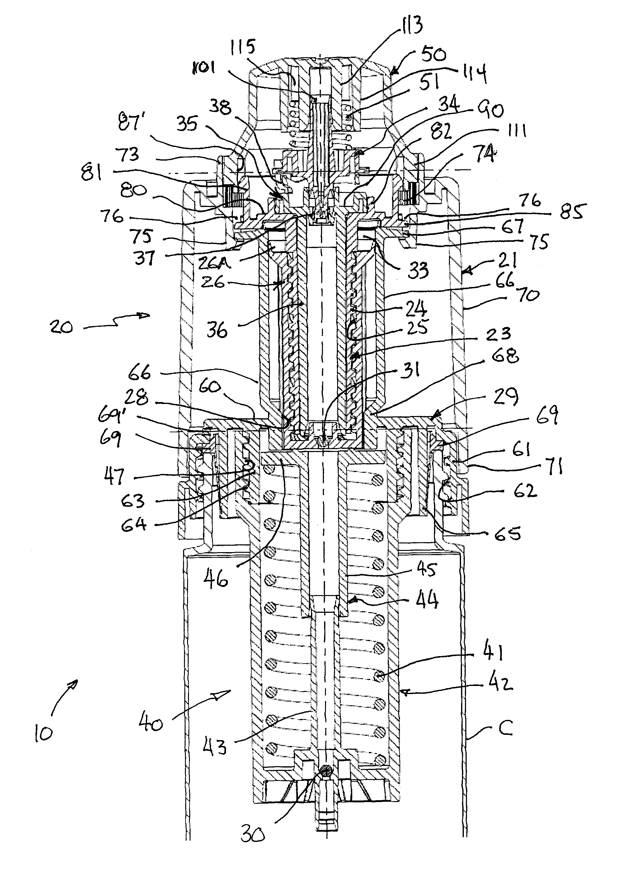
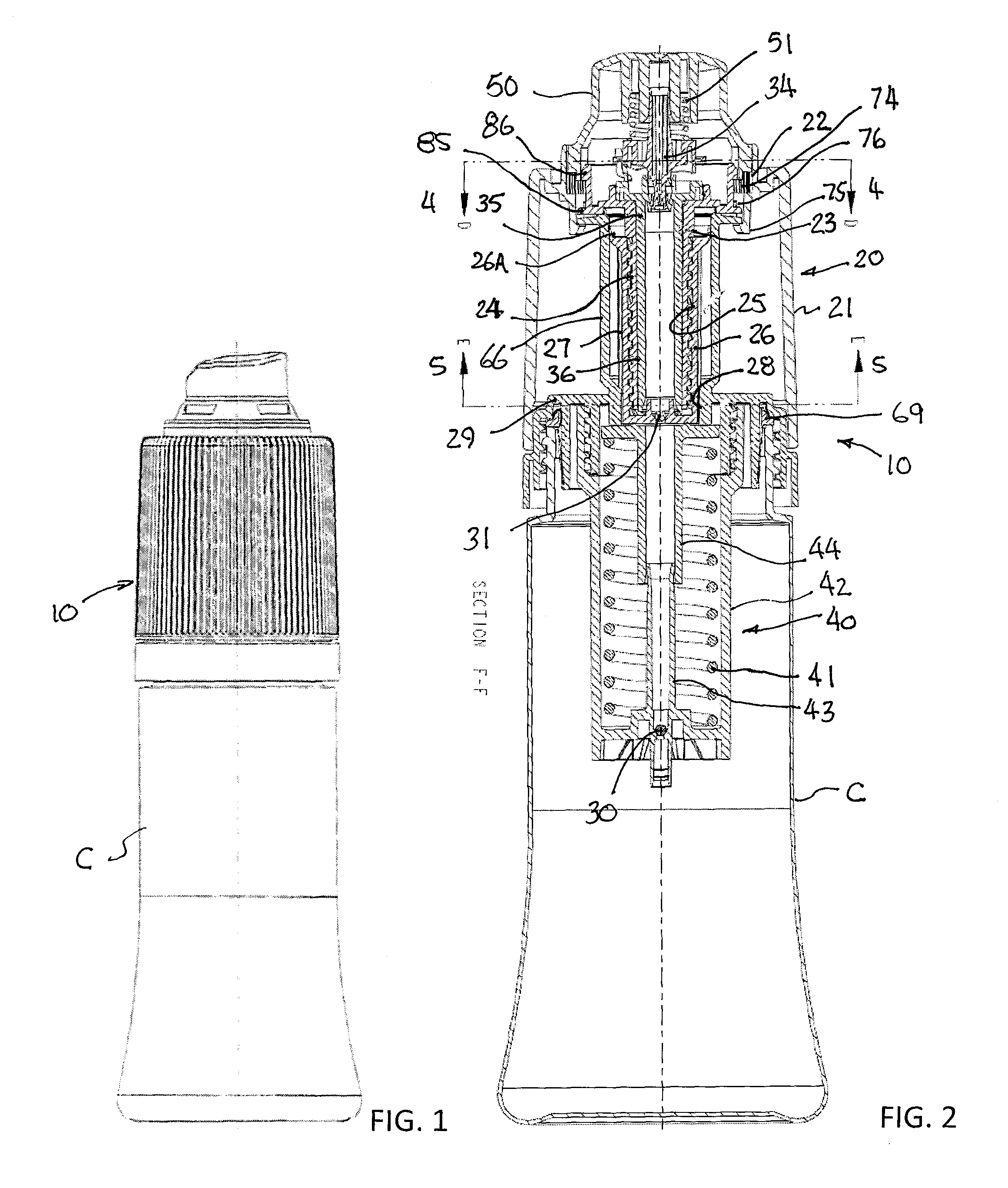
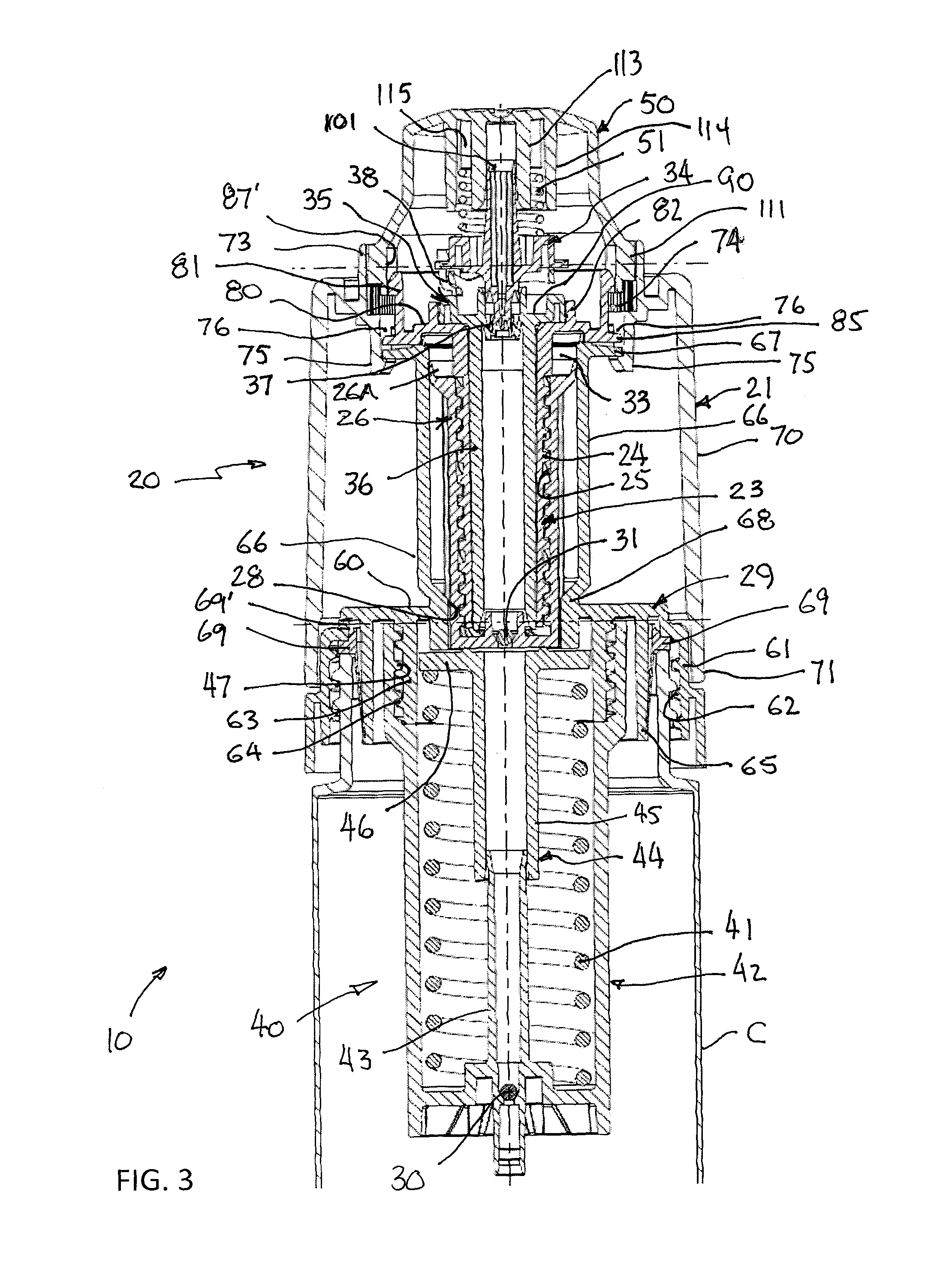
[0092]A first preferred embodiment of the invention is shown in FIGS. 1-18. In this form of the invention, a power assembly 10 comprising a pump mechanism 20 and spring mechanism 40 is mounted to a container C for dispensing product (not shown) from the container.

[0093]As seen best in FIGS. 1-7B, 9A and 9B, the pump mechanism 20 comprises a rotatable actuating collar 21 connected through an escapement mechanism 22 with a drive screw 23 that has an externally threaded tubular shaft 24 engaged with internal threads 25 in a hollow tube-shaped piston 26 having a sliding seal 26A on its upper end. Axial splines 27 on the outer surface of the piston are engaged with mating axial splines 28 in a cap cylinder 29 mounted on the open upper end of a container C. The splines prevent rotation of the piston so that when the drive screw is rotated by the actuating collar through a full turn the piston is caused to reciprocate from a first, at-rest position as seen in FIG. 3 to a second, primed pos...


PUM

PropertyMeasurementUnit
pressureaaaaaaaaaa
power assemblyaaaaaaaaaa
rotationaaaaaaaaaa

Abstract

A power assembly for dispensing product from a container includes a pump mechanism and an energy storage mechanism. The pump mechanism includes a rotatable actuating collar connected through an escapement mechanism with a drive screw with an externally threaded shaft engaged with internal threads in a piston. Rotation of the collar reciprocates the piston to store energy in the energy storage mechanism and to draw product into a pump chamber from which the product is dispensed. An actuator is connected with a stem valve to open it when the actuator is depressed, enabling the energy storage mechanism to push the piston back to its at-rest position to force product from the pump chamber and ready it for another dispensing cycle. Disengagement of the escapement mechanism when the actuator is depressed prevents rotation of the actuating collar. Different energy storage mechanisms can be interchangeably attached to the pump mechanism.

Description

BACKGROUND OF THE INVENTION[0001]1. Field of the Invention[0002]The present invention relates to dispensers, specifically to duration spray dispensers that are energized mechanically and pressurized by a non-chemical means.[0003]2. Description of Related Art[0004]Both chemically driven and mechanically operated spray dispensers have been in use for many years and are still popular Due to their convenience. However, aerosol dispensers that use chemical propellants have come under increasing scrutiny and restrictions are being imposed upon them due to their adverse impact upon the environment as well as the hazards associated with handling them and related insurance issues. Also, conventional non-chemical mechanical spray dispensers are typically unfavorably compared with chemically driven aerosols because they are bulky and commonly require multiple steps in their operation, making them difficult to operate, especially by persons suffering from a disability such as arthritis. They al...

Claims


Application Information

Patent Timeline
Patent Type & Authority Patents(United States)
IPC IPC(8): G01F11/06
CPCG01F11/025B65D31/04B65D33/01B65D75/5877B65D85/72B05B11/1052B05B11/1069B05B11/1073B05B11/1074B05B11/1078B05B11/1091B05B9/0883B05B11/1076
Inventor BLAKE, WILLIAM SYDNEY
Owner ALTERNATIVE PACKAGING SOLUTIONS
Why Eureka
Try Eureka