
Cold storage doorway with airflow control system and method

a control system and cold storage technology, applied in the field of cold storage vestibules with airflow control systems, can solve the problems of multiple air curtain arrangements, complex situation, and inability to operate efficiently or even properly in multiple air curtain arrangements

Active Publication Date: 2012-10-16
HCR
View PDF35 Cites 3 Cited by
  • Summary
  • Abstract
  • Description
  • Claims
  • Application Information

AI Technical Summary

Benefits of technology

"The present invention provides an air curtain and method for dynamically conditioning air in a cold storage doorway. The air curtain arrangement includes a discharge means that directs an air stream across the doorway and a control unit that monitors the air stream temperature and operates the heater to maintain the air stream temperature in a non-saturated state. The air curtain arrangement can also include an air return means that receives the air discharged across the doorway and an air sensor to provide input to the control unit. The technical effects of the invention include improved air conditioning and dynamic temperature control for cold storage doorways, as well as improved energy efficiency and comfort for users."

Problems solved by technology

In changing environments, this permits the formation of ice, water, and fog because the system may not respond as quickly as the conditions change and because the sensors may not be sufficiently accurate for all positions in the vestibule.
This is particularly a problem for systems that rely upon mathematical approximations of the psychrometric saturation curve.
Also, conventional control systems do not apply to multiple air curtain arrangements.
Multiple air curtain arrangements—particularly those having three or more air curtains—present a more complex situation than do single air curtains.
As a result, conventional systems for dynamically conditioning air do not operate efficiently, or even properly, in multiple air curtain arrangements.

Method used


Image

  • Cold storage doorway with airflow control system and method
  • Cold storage doorway with airflow control system and method
  • Cold storage doorway with airflow control system and method

Examples


Embodiment Construction

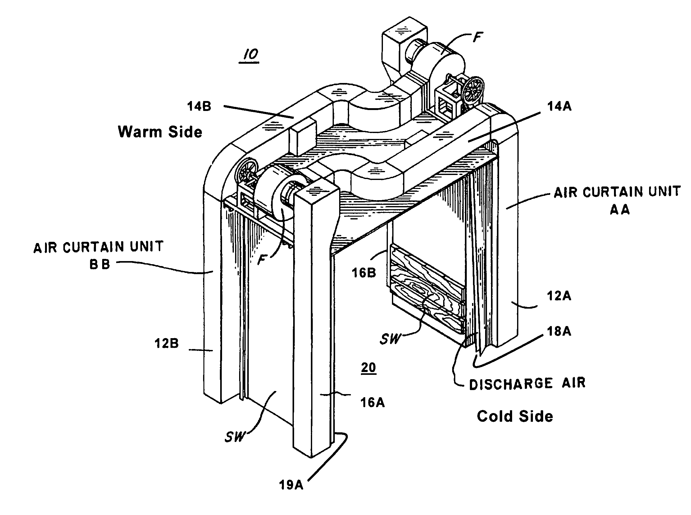
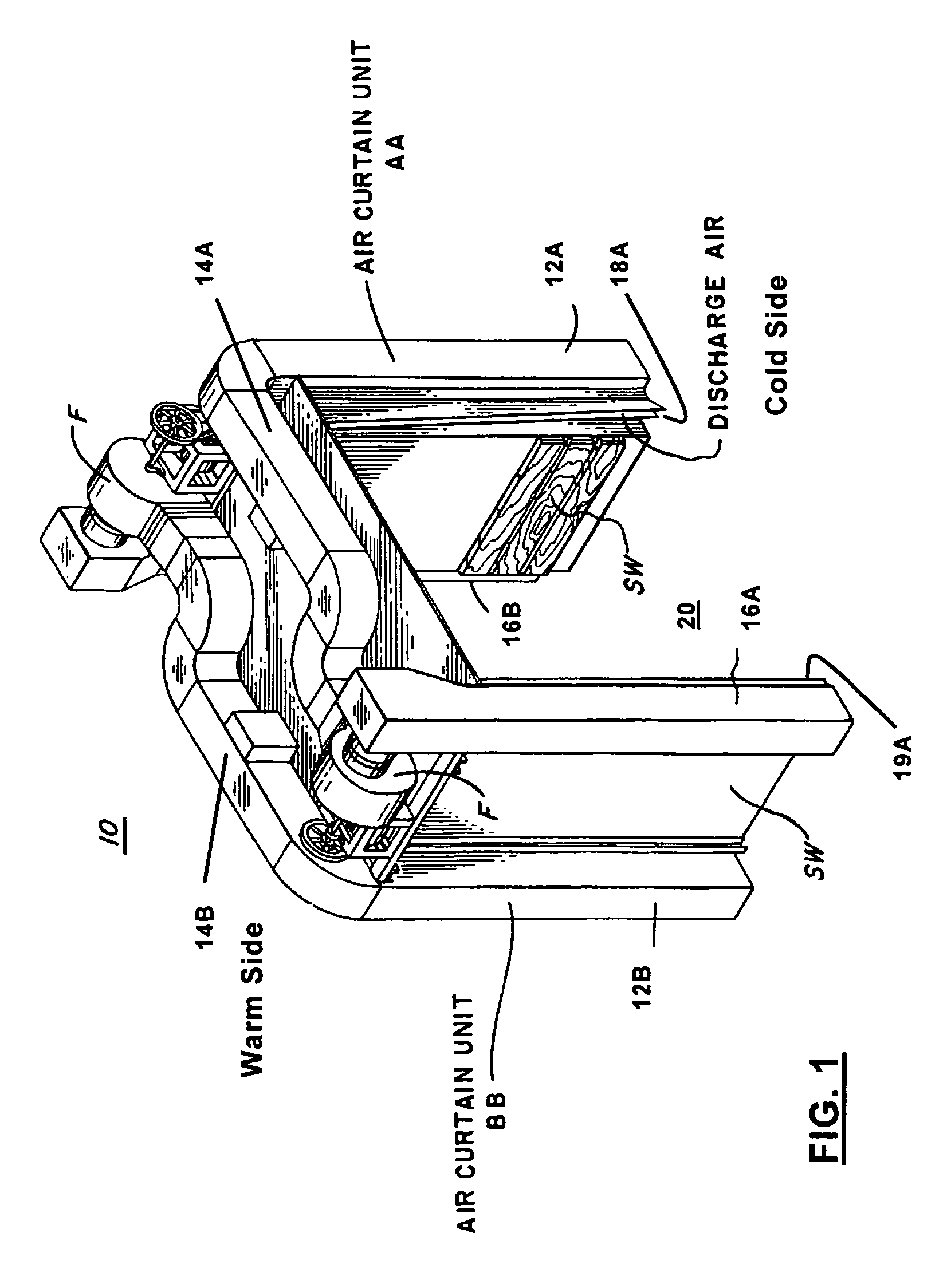
[0031]FIG. 1 shows a perspective view of one embodiment of an air curtain arrangement 10 according to the present invention. Embodiments of an air curtain arrangement may include one or more air curtain units (e.g., AA, BB in FIG. 1). As used herein, an air curtain unit (or air curtain) refers to an apparatus having at least a supply air plenum 12A, 12B with an outlet aperture 18A that discharges air across the doorway 20, a return air duct 16A, 16B with an inlet aperture (not shown) that receives the air discharged across the doorway 20, and an intermediate air duct 14A, 14B extending between the supply plenum 12A, 12B and return air duct 16A, 16B, or equivalent components. Air curtains may direct air across the doorway 20 horizontally, vertically, or otherwise. Air curtain arrangements having two or more air curtains are sometimes referred to as “vestibules.” Vestibules having multiple air curtains may use different types of air curtains or air curtains in different configurations...


PUM


Abstract

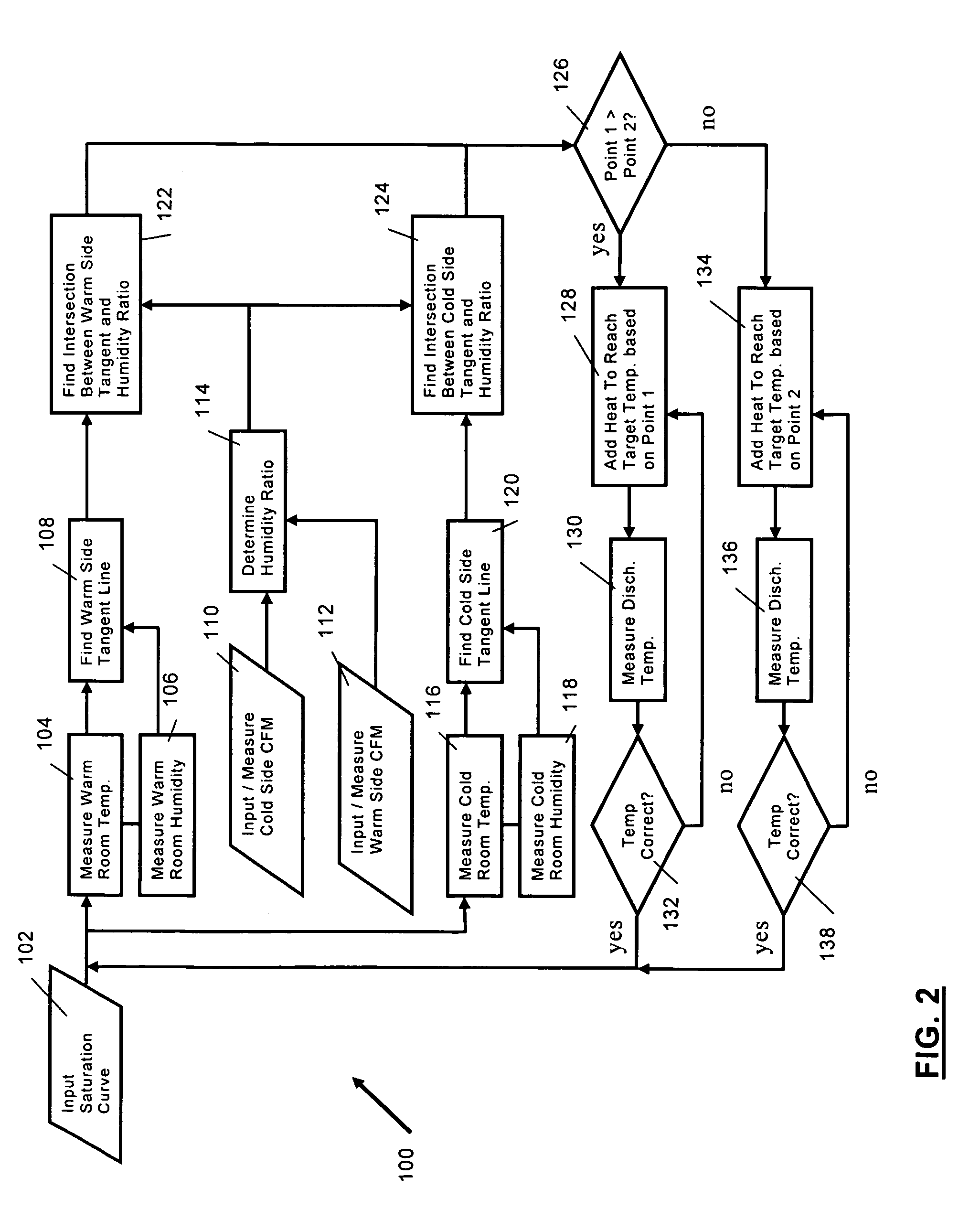
A conditioned vestibule, control system, and method are disclosed for use with a cold storage doorway that separates warm and cold sides. A heater warms an air stream discharged across the doorway by the vestibule. A control unit operates the heater to maintain an air stream temperature. The control unit continuously monitors the air stream temperature and operates the heater to maintain the air stream temperature in a non-saturated state based on a humidity ratio. One embodiment calculates first and second temperatures based, respectively, warm and cold side tangent lines to a psychrometric saturation curve and based on the humidity ratio. The tangent lines are based on humidity and temperature sensed on the warm and cold sides. The air stream is warmed to at least the greater of the first and second temperatures. One embodiment controls air flow to adjust the humidity ratio to more efficiently operate the vestibule.

Description

FIELD OF INVENTION[0001]The present invention relates to a conditioned vestibule for a cold storage doorway. More particularly, the present invention relates to an air curtain arrangement and control system that controls temperature of the air discharged across a doorway and a method of controlling the airflow temperature.BACKGROUND INFORMATION[0002]In the field of large cold storage freezers and similar devices, various systems such as solid doors, strip curtains, and air curtains, may be used to separate the cold storage room from an adjacent relatively warm anteroom. It is desirable to allow traffic from people and equipment through a doorway between the cold storage room and the adjacent warm room safely and with a minimum transfer of cool air from the cold room to the warm room.[0003]The use of air curtains is one method of allowing a doorway to remain open to traffic while also preventing substantial energy loss between the cold and warm sides of the vestibule. Air curtains ge...

Claims


Application Information

Patent Timeline
Patent Type & Authority Patents(United States)
IPC IPC(8): F24F9/00
CPCA61N7/02A61B2017/00084A61B2017/00128A61B2017/00774A61M37/0092A61B2017/00734
Inventor SMITH, PETERRHYNER, DANIEL J.STEELE, CARL E.
Owner HCR
Learn More