Multi-band antenna for satellite positioning system

a satellite positioning system and antenna technology, applied in the direction of antennas, antenna supports/mountings, radiating element structural forms, etc., can solve the problems of limiting the determination of position, multipath effects and phase-centre stability, and the difficulty of the receiver to mitigate the effect of multipath, so as to achieve less costly electric circuits, stable and compact

Active Publication Date: 2012-10-16
THE EURO UNION REPRESENTED BY THE EURO CO
View PDF20 Cites 7 Cited by
  • Summary
  • Abstract
  • Description
  • Claims
  • Application Information

AI Technical Summary

Benefits of technology

[0011]Such a stacked multi-band antenna for a satellite positioning system comprises a stack of conductive patches, which are each dimensioned so as to be respectively operative in a dedicated frequency band. According to an important aspect of the invention, an excitation line section, which comprises pairs of conductive strips, is arranged underneath said stack of conductive patches. Each pair of conductive strips is adapted for radiatively coupling to an associate conductive patch of the stack of conductive patches. The antenna further comprises an RF front end with at least one electric circuit arranged in a triplate section underneath the excitation line section for operatively connecting the pairs of conductive strips to a satellite positioning receiver. The at least one electric circuit includes filters and amplifiers for respectively filtering and amplifying signals from the pairs of conductive strips, during antenna operation. The RF front end preferably has separate circuits for the different frequency bands. This allows independent impedance matching, feeding, filtering and amplifying. In case of two frequency bands, the antenna thus presents self-diplexing properties. The triplate shields the at least one electric circuit. Most preferably, the conductive strips of each pair of conductive strips are substantially orthogonal one to the other. When circular-polarised signals are received or emitted, the signals in the conductive strips of each pair of conductive strips have a phase difference of 90 degrees. The compact configuration of the antenna provides high phase-centre stability.
[0015]The circuits preferably comprise an impedance matching network, a feeding network, at least one filtering stage and low-noise amplifiers. Each circuit can be optimised so as to present maximal transmission of signals of the respective frequency band, while out-of-band signals are reflected or attenuated. The matching, feeding and amplification components can be chosen so that they present additional filtering capabilities in the respective frequency band. Consequently, the specifications for the filtering stage itself may be relaxed, which may result in more compact, stable and less costly electric circuits.
[0016]In order to adapt the electric circuits for circular-polarised signals, the first electric circuit comprises a first coupling stage for combining first frequency signals to or from the first strip of the first pair of conductive strips and first frequency signals to or from the second strip of the first pair of conductive strips with a relative phase difference of 90 degrees and the second electric circuit comprises a second coupling stage for combining second frequency signals to or from the first strip of the second pair of conductive strips and second frequency signals to or from the second strip of the second pair of conductive strips with a relative phase difference of 90 degrees. The skilled person will note that each coupling stage can comprise one or more than one couplers, for instance three couplers, in each of said first and second electric circuit. A balanced excitation or sensitivity with respect to the first frequency signals and the second frequency signals can thereby be achieved.
[0018]When appropriate, at least the second electric circuit can comprise a diplexer with two band-pass filters for selecting two narrower frequency bands within the second frequency band. If, for instance, the second frequency band contains the E5 band and the E6 band, E5 signals can be filtered separately from the E6 signals, which results in an improved signal-to-noise ratio.

Problems solved by technology

Important issues in satellite positioning systems are multipath effects and phase-centre stability.
Multipath signals are due to reflections at surfaces in the surroundings of the antenna and they constitute a limiting factor for the determination of position.
The nearer the reflecting surface is to the antenna, the more difficult it becomes for the receiver to mitigate the effect of multipath.
Additionally, out-of-band rejection shall be very high, especially if the antenna is to be used in an environment with high RF interference levels, such as e.g. avionics.
Group delay is mainly due to those parts of electric circuits that are based on resonant sections.

Method used


Image

  • Multi-band antenna for satellite positioning system
  • Multi-band antenna for satellite positioning system
  • Multi-band antenna for satellite positioning system

Examples


Embodiment Construction

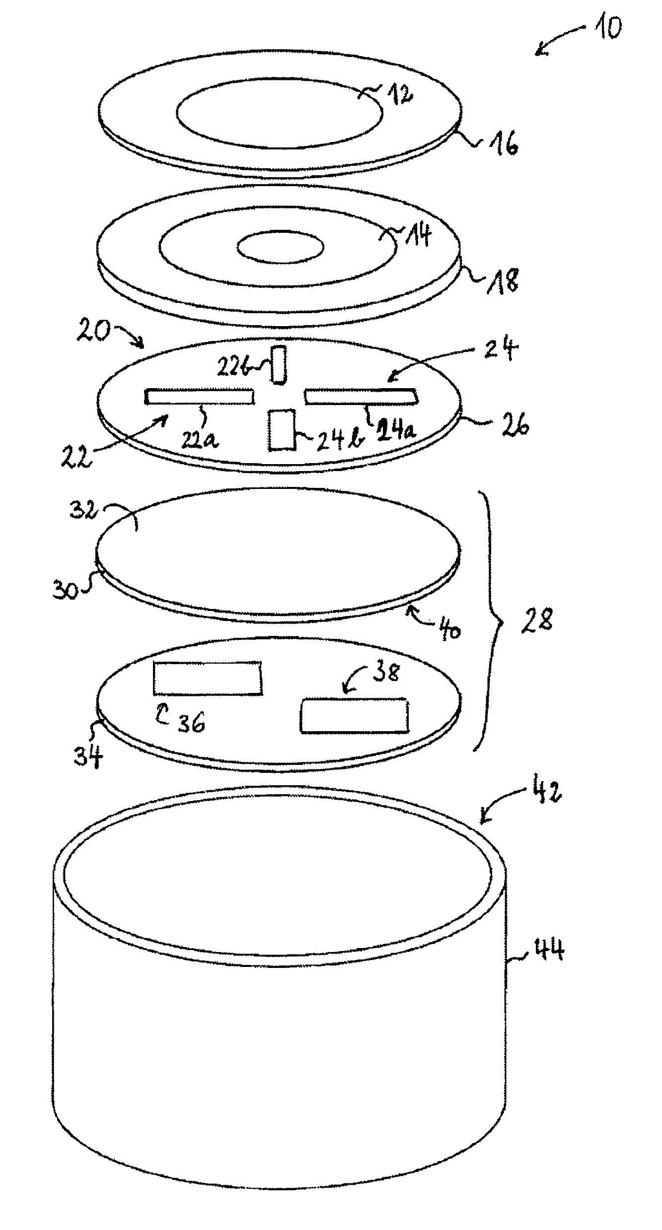
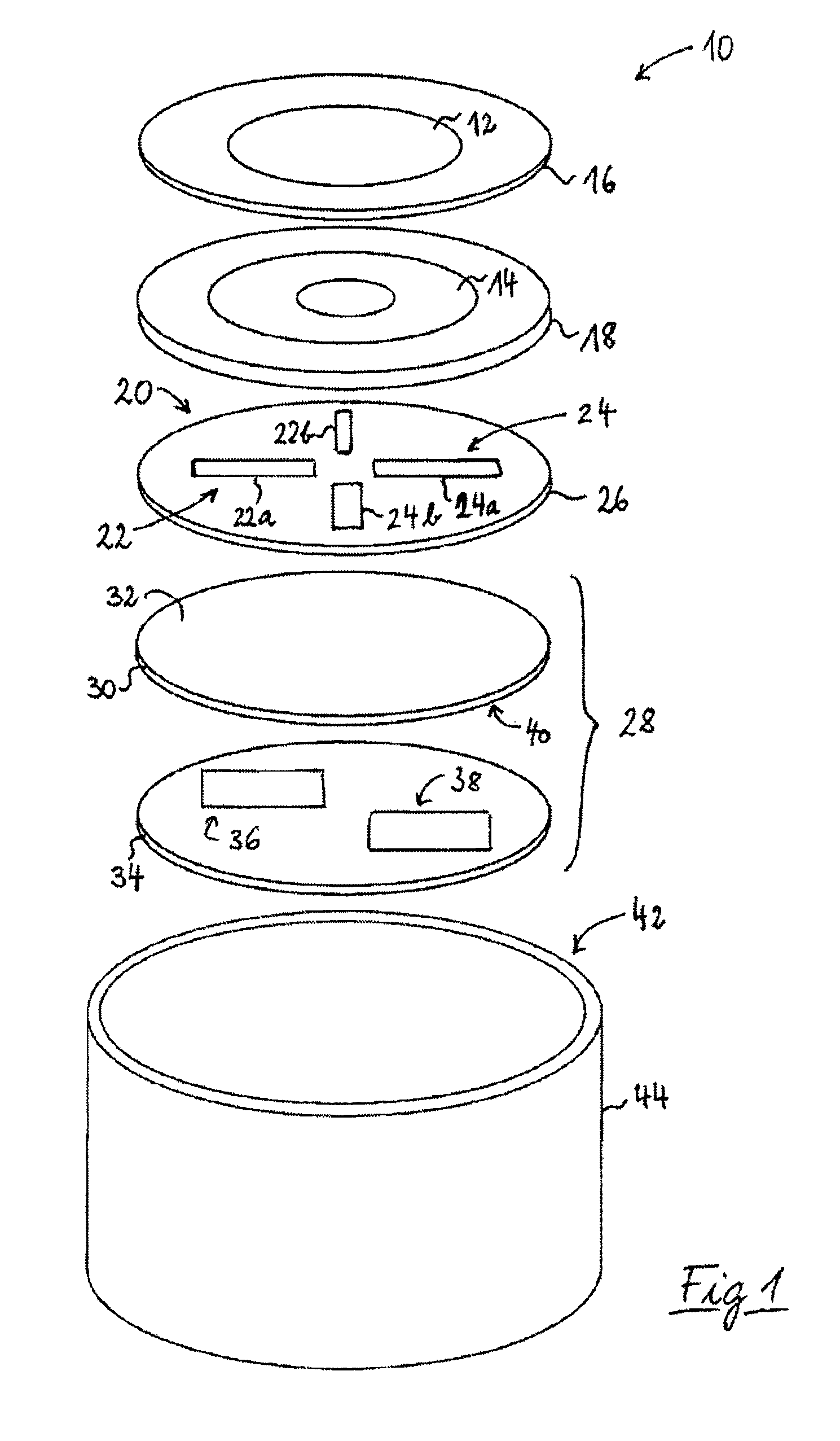
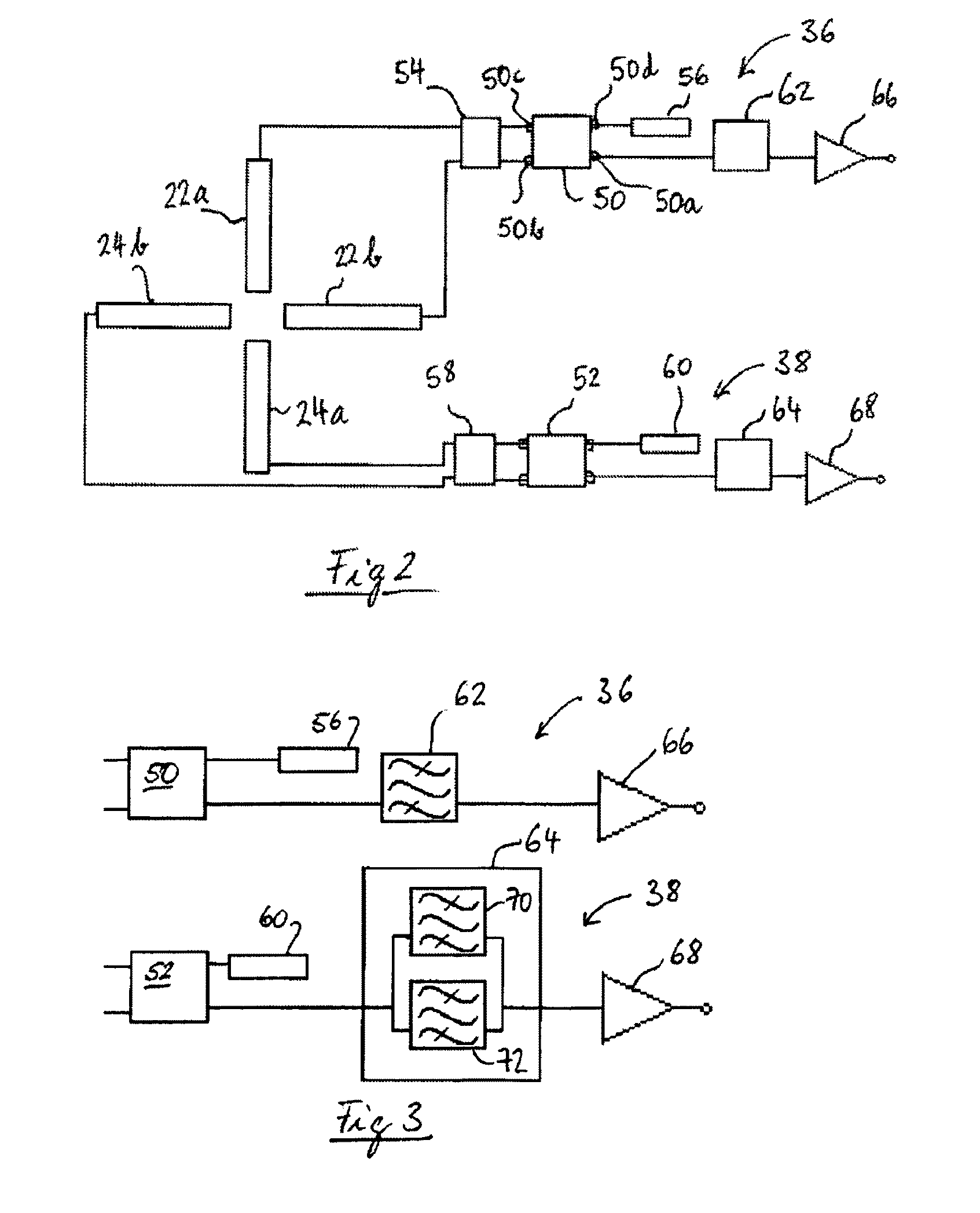
[0032]An schematic view of a preferred embodiment of a stacked multi-band patch antenna 10 is shown in FIG. 1. The antenna comprises a stack of conductive patches 12, 14 applied each on a disk-shaped dielectric substrate 16, 18. Underneath the stacked patches an excitation line section 20 comprises two pairs 22, 24 of conductive strips 22a, 22b, 24a, 24b on a dielectric substrate 26. The conductive strips 22a, 22b, 24a, 24b are connected with an RF front end arranged in a triplate 28 under the excitation line section 20. The conductive patches 12, 14, the excitation line section 20 and the triplate 28 are arranged in substantially parallel relationship.

[0033]The conductive patches 12, 14 and the conductive strips 22a, 22b, 24a, 24b of the excitation section 20 are manufactured as printed copper layers, which can be plated with a tin-lead alloy. Alternatively, an alloy without lead can be used.

[0034]The top conductive patch 12 is a disk-shaped copper patch on a first dielectric disk ...


PUM


Abstract

A stacked multi-band antenna for a satellite positioning system comprises a stack of conductive patches, which are each dimensioned so as to be respectively operative in a dedicated frequency band. An excitation line section comprising pairs of conductive strips is arranged underneath the stack of conductive patches. Each pair of conductive strips is adapted for radiatively coupling to an associate conductive patch of the stack of conductive patches. An RF front end with at least one electric circuit is arranged in a triplate section underneath the excitation line section for operatively connecting the pairs of conductive strips to a satellite positioning receiver. The at least one electric circuit includes filters and amplifiers for respectively filtering and amplifying signals from the pairs of conductive strips, during antenna operation.

Description

CROSS-REFERENCE TO RELATED APPLICATIONS[0001]The present application is a national stage application of PCT / EP2006 / 064067, filed Jul. 10, 2006, which claims priority to EP 05106370.9, filed on Jul. 12, 2005. The content of both of these applications is incorporated herein by reference.TECHNICAL FIELD OF THE INVENTION[0002]The present invention relates to an antenna for a satellite positioning system, more particularly to a multi-band stacked-patch antenna.BACKGROUND OF THE INVENTION[0003]Satellite navigation systems operate in multiple frequency bands in order to reduce multipath effects and ionospheric or tropospheric errors so as to ultimately provide enhanced positioning accuracy to the user. The existing GPS (Global Positioning System), for instance, uses signals in the L1 frequency band, centred at 1575.42 MHz, and in the L2 band, centred at 1227.6 MHz. The coming European Galileo positioning system will operate in a different set of frequency bands, e.g. the E5 band (1164-1215...

Claims


Application Information

Patent Timeline
Patent Type & Authority Patents(United States)
IPC IPC(8): H01Q1/38H01Q5/40
CPCH01Q9/0414H01Q9/0435H01Q5/40H01Q9/0464H01Q9/0457H01Q5/00H01Q1/38H01Q9/04
Inventor DUCHESNE, LUCLE GOFF, MARCFOGED, LARSBARACCO, JEAN-MARC
Owner THE EURO UNION REPRESENTED BY THE EURO CO
Why Eureka
Try Eureka