Aeration unit, aeration apparatus equipped therewith and method of aeration

a technology of aeration apparatus and aeration unit, which is applied in the direction of carburetizing air, dissolving, and separation processes, etc., can solve the problems of inability to make water quality in a tank suitable for aquatic organisms, low efficiency of oxygen supply, and inferior gas dissolution balance, etc., to achieve excellent economic efficiency, simple structure, and efficient use of energy

Active Publication Date: 2012-10-23
MA JUN +2
View PDF8 Cites 12 Cited by
  • Summary
  • Abstract
  • Description
  • Claims
  • Application Information

AI Technical Summary

Benefits of technology

[0027]The aeration unit in the first aspect of the present invention has the following effects.
[0028](a) Liquid foam bodies are generated from bubbles produced by an air diffuser by way of liquid foam, thus making it possible to give surrounding water of ascending bubbles as a water film on the surface of liquid foam bodies. Further, the liquid foam bodies are exposed to gas retained in water and burst, by which the gas can be dissolved in the water film depending on a pressure of the thus retained gas. Therefore, the aeration unit is excellent in energy savings.
[0029](b) Since the gas used in gas dissolution inside the gas retention chamber can be released again into water to generate new bubbles, the aeration unit is able to use energy efficiently and is excellent in economic efficiency.
[0030]The aeration unit in the second aspect of the present invention has the following effects.
[0031](a) Siphon phenomena inside the aeration unit are kept, by which water brought together on ascending of bubbles inside the liquid foam generating channel part is increased in amount, thus making it possible to increase an amount of treated water. Therefore, the aeration unit is excellent in energy savings and economic efficiency.
[0032](b) Treated water by aeration through generation of liquid foam inside the aeration unit can be moved to any desired place due to gravitational force resulting from a hydraulic head difference inside the aeration unit.

Problems solved by technology

However, in the above-described conventional air diffusers, aeration apparatuses and methods of aeration described in Publication Nos. 2006-326524 and 2004-141730, a gas dissolution method based on the fact that gas is made smaller in size to increase the contact area of gas with liquid to prolong the contact time of gas with liquid is adopted, thereby posing a problem that oxygen is supplied at an extremely low efficiency.
Further, where conventional aeration is repeated in which pressure is applied to air inside a water tank having aquatic organisms, these organisms consume oxygen gas of gas components dissolved in water, thereby the water of the tank is finally changed into that containing a large amount of unnecessary gases such as nitrogen gas and is inferior in gas dissolution balance.
In other words, there is a problem that the above method is unable to make water quality in a tank appropriate for aquatic organisms.

Method used


Image

  • Aeration unit, aeration apparatus equipped therewith and method of aeration
  • Aeration unit, aeration apparatus equipped therewith and method of aeration
  • Aeration unit, aeration apparatus equipped therewith and method of aeration

Examples


first embodiment

[0104](First Embodiment)

[0105]Hereinafter, a detailed description will be given for an aeration apparatus equipped with an aeration unit of a first embodiment in the present invention by referring to FIG. 1 to FIG. 8.

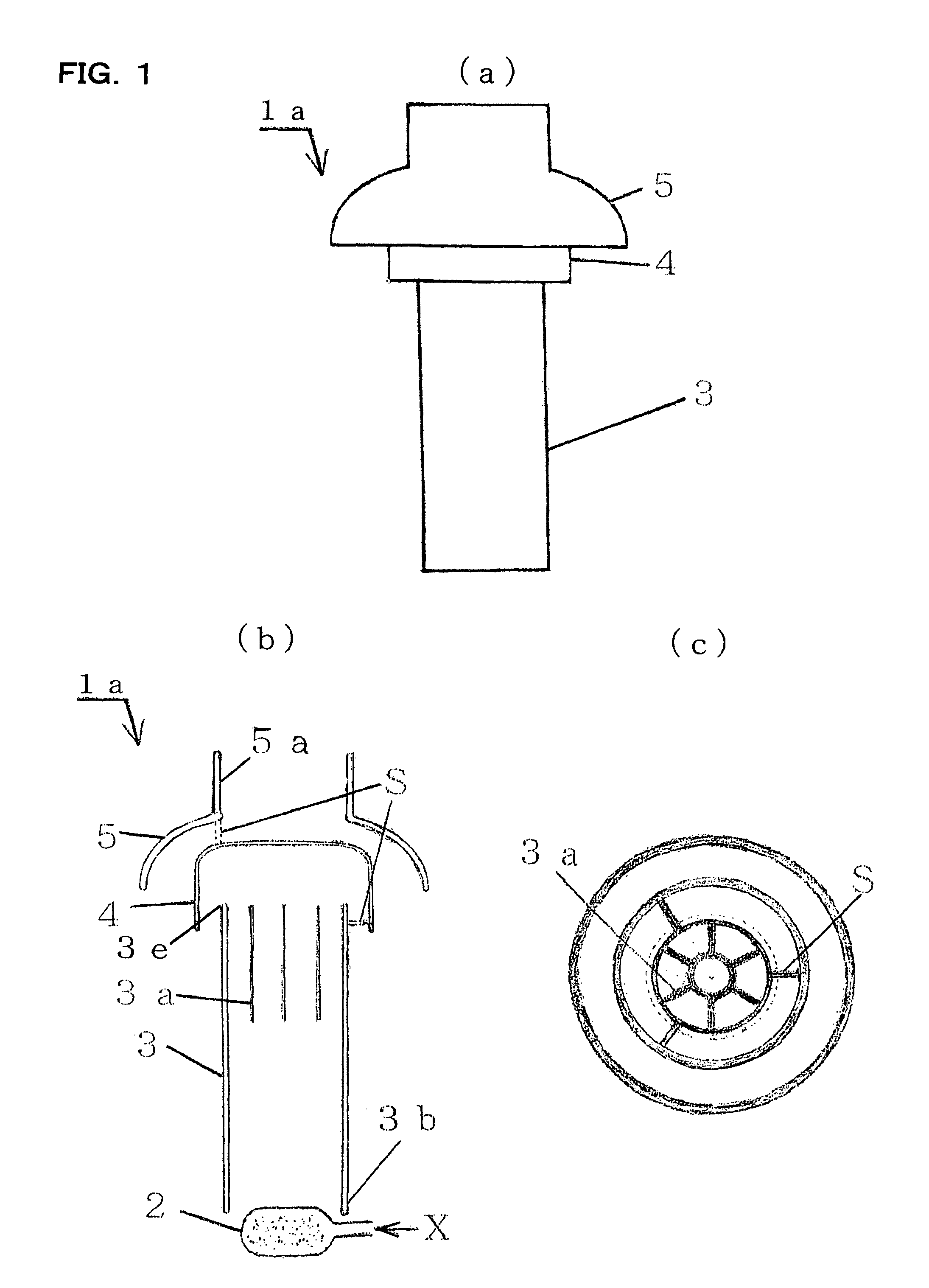
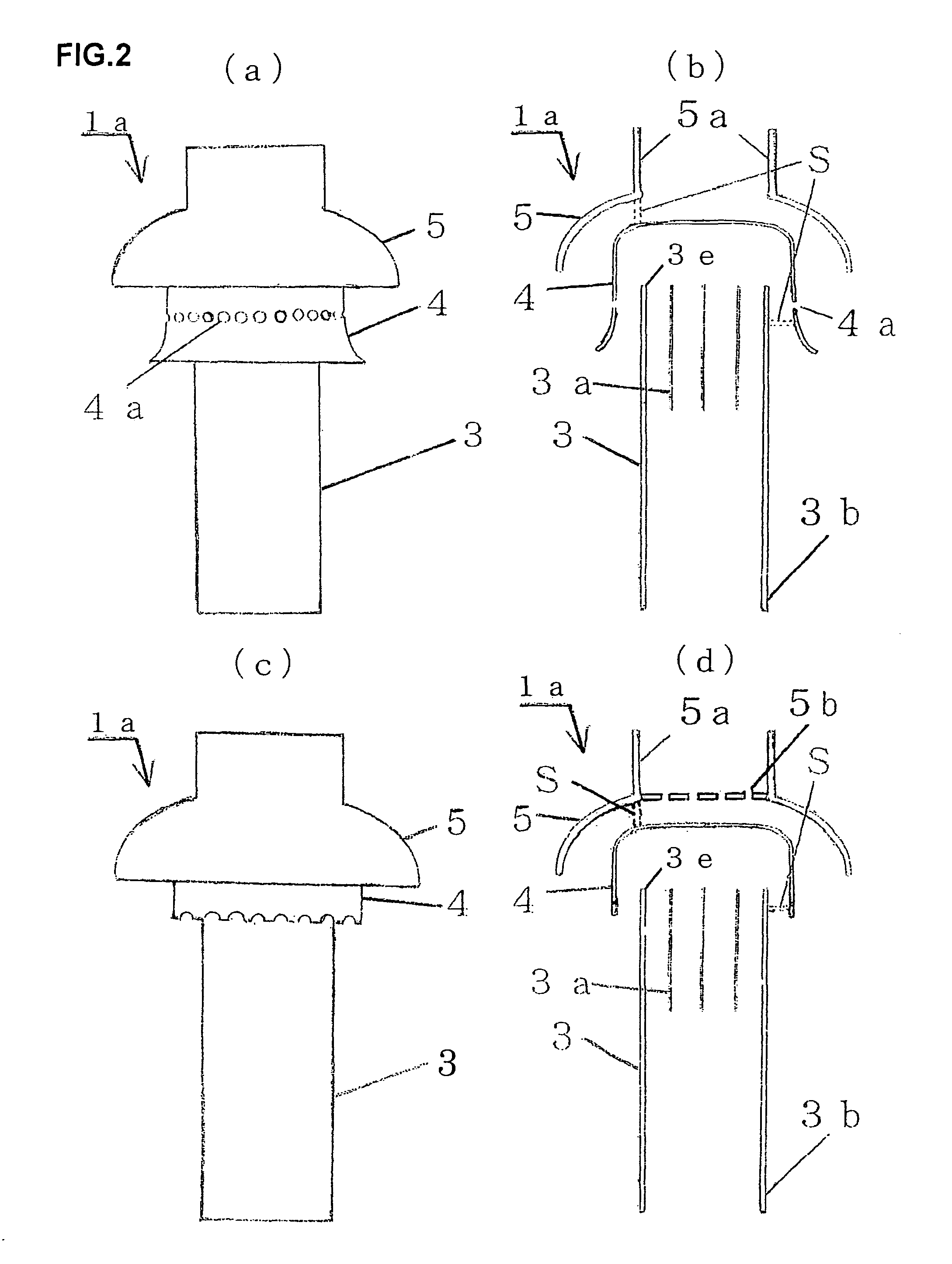
[0106]FIGS. 1(a) to 1(c) are respectively an external view, a longitudinal sectional view and a transverse sectional view of the aeration unit of the first embodiment in the present invention.

[0107]In FIGS. 1(a) to 1(c), the reference numeral 1a denotes an aeration unit; 2 is an air diffuser for producing bubbles in water; 3 is a cylindrically-shaped liquid foam generating channel part made so that bubbles can ascend thereinside; and 3a denotes a generating channel for easily generating liquid foam bodies from bubbles ascending in water. The reference numeral 3b is a lower end of the liquid foam generating channel part 3 at which a joint part used in connecting the other aeration unit is formed. The reference numeral 4 denotes a cup-shaped gas retention chamber having a...

second embodiment

[0127](Second Embodiment)

[0128]Hereinafter, a detailed description will be given for an aeration unit and an aeration apparatus of a second embodiment of the present invention by referring to FIG. 9 to FIG. 13.

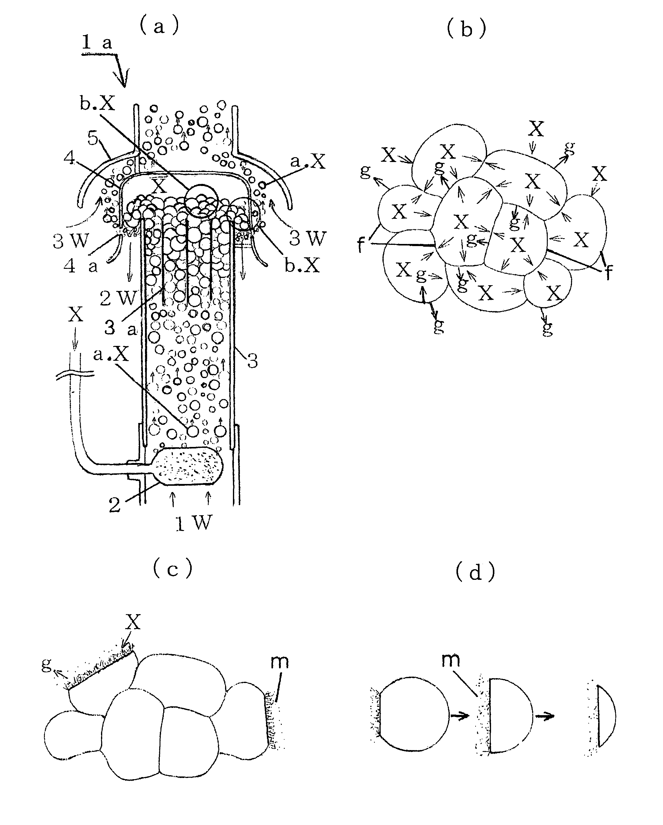
[0129]FIG. 9 is a schematic view showing behavior of bubbles inside the aeration unit 1b of the second embodiment in the present invention.

[0130]The reference numeral 1W depicts surrounding water (water to be treated) entrained with bubbles a. X ascending inside a liquid foam generating channel part 3; 3a is a generating channel for easily generating liquid foam bodies b. X from bubbles ascending in water; 4 depicts a cup-shaped gas retention chamber having a space thereinside so as to retain gas in water; 4G is a range of a siphon gas retention chamber part; 3c is a siphon part installed below the gas retention chamber 4 in such a manner that separated water 2WA generated by bursting of liquid foam bodies b. X descends thereinside; 2W denotes treated water which is aerated by...


PUM

PropertyMeasurementUnit
diameteraaaaaaaaaa
temperatureaaaaaaaaaa
diametersaaaaaaaaaa

Abstract

An aeration unit, an aeration apparatus and a method of aeration are provided that can quickly realize water quality with gas dissolution balance appropriate for living creatures in water, and that can be utilized for treating polluted water at sewage treatment facilities and used in a gas-liquid contact step at chemical plants or others. A multiple stage aeration apparatus constituted with an air diffuser for producing bubbles in water, a liquid foam generating channel part for changing bubbles in water into liquid foam bodies (soap-bubble-like liquid foam aggregate), a gas retention chamber having a space capable of retaining gas in water and a bubble accumulating part for collecting bubbles newly released from below the gas retention chamber and feeding the bubbles to the liquid foam generating channel part connected to the upper part thereof is disclosed.

Description

TECHNICAL FIELD[0001]The present invention relates to an aeration unit, an aeration apparatus equipped with the aeration unit, and a method of aeration which change bubbles such as oxygen and air released from air diffusing pipes under water mainly in lakes, ponds, fish-and-shellfish breeding ponds, polluted water treatment facilities or the like into liquid foam, thereby generating liquid foam bodies (soap-bubble-like liquid foam aggregate), thus enabling the realization of water quality with gas dissolution balance appropriate for aquatic organisms, and, in particular, to an aeration unit, an aeration apparatus equipped with the aeration unit and a method of aeration which can be utilized in a gas liquid contact step in chemical plants and in treatment of polluted water in sewage treatment facilities or the like.BACKGROUND ART[0002]An aeration apparatus and a method of aeration conventionally used in lakes, ponds, fish-and-shellfish breeding ponds, polluted water treatment facilit...

Claims


Application Information

Patent Timeline
Patent Type & Authority Patents(United States)
IPC IPC(8): B01F3/04
CPCA01K63/042B01F3/04262B01F3/04517B01F3/04524C02F7/00C02F1/74C02F3/20B01F2003/04148B01F2003/04361B01F2003/04141Y02W10/10B01F23/231122B01F23/23113B01F23/23123B01F23/231231B01F23/232312B01F23/232311A01K63/04B01F21/00B01F23/20
Inventor FUJISATO, TETSUHIKOMA, JUN
Owner MA JUN
Why Eureka
Try Eureka