Mount and bearing for shock absorber

a technology for shock absorbers and bearings, which is applied in the direction of shock absorbers, transportation items, loading/unloading vehicle arrangments, etc., can solve the problems of airbag failure, air line failure, airbag failure, etc., and achieve the effect of less expensive and more efficien

Active Publication Date: 2012-10-23
ARNOTT T&P HLDG LLC
View PDF26 Cites 14 Cited by
  • Summary
  • Abstract
  • Description
  • Claims
  • Application Information

AI Technical Summary

Benefits of technology

[0009]A primary objective of the present invention is to provide improved mount and bearing height adjustable air suspension shock absorber devices, apparatus, syste

Problems solved by technology

These sophisticated types of air suspension systems can have numerous problems, such as air bag failure, air line failure, compressor failure and dryer type failures.
Air bag type failures can be caused by wet rot, due to old age, or moisture within the air system that damages it from the inside.
Air ride suspension parts can fail because rubber dries out.
Improper installation can cause the air bags to rub against the vehicle's frame or other surrounding parts, damaging it.
Overextension of an air spring which is not constrained by other suspension components such as a shock absorber may also lead to the premature failure of an air spring through the tearing of the flexible layers.
Air line failure is a failure of the tubing which connects the air bags or struts to the rest of the air system, and such as a DOT (Department of Transportation)-approved nylon air brake line.
This type of failure can occur when air lines, which must be routed to the air bags through the chassis of the vehicle, rub against a sharp edge of a chassis member or a moving suspension component, causing a hole to be formed.
This mode of failure will typically take some time to occur after the

Method used


Image

  • Mount and bearing for shock absorber
  • Mount and bearing for shock absorber
  • Mount and bearing for shock absorber

Examples


Embodiment Construction

[0042]Before explaining the disclosed embodiments of the present invention in detail it is to be understood that the invention is not limited in its applications to the details of the particular arrangements shown since the invention is capable of other embodiments. Also, the terminology used herein is for the purpose of description and not of limitation.

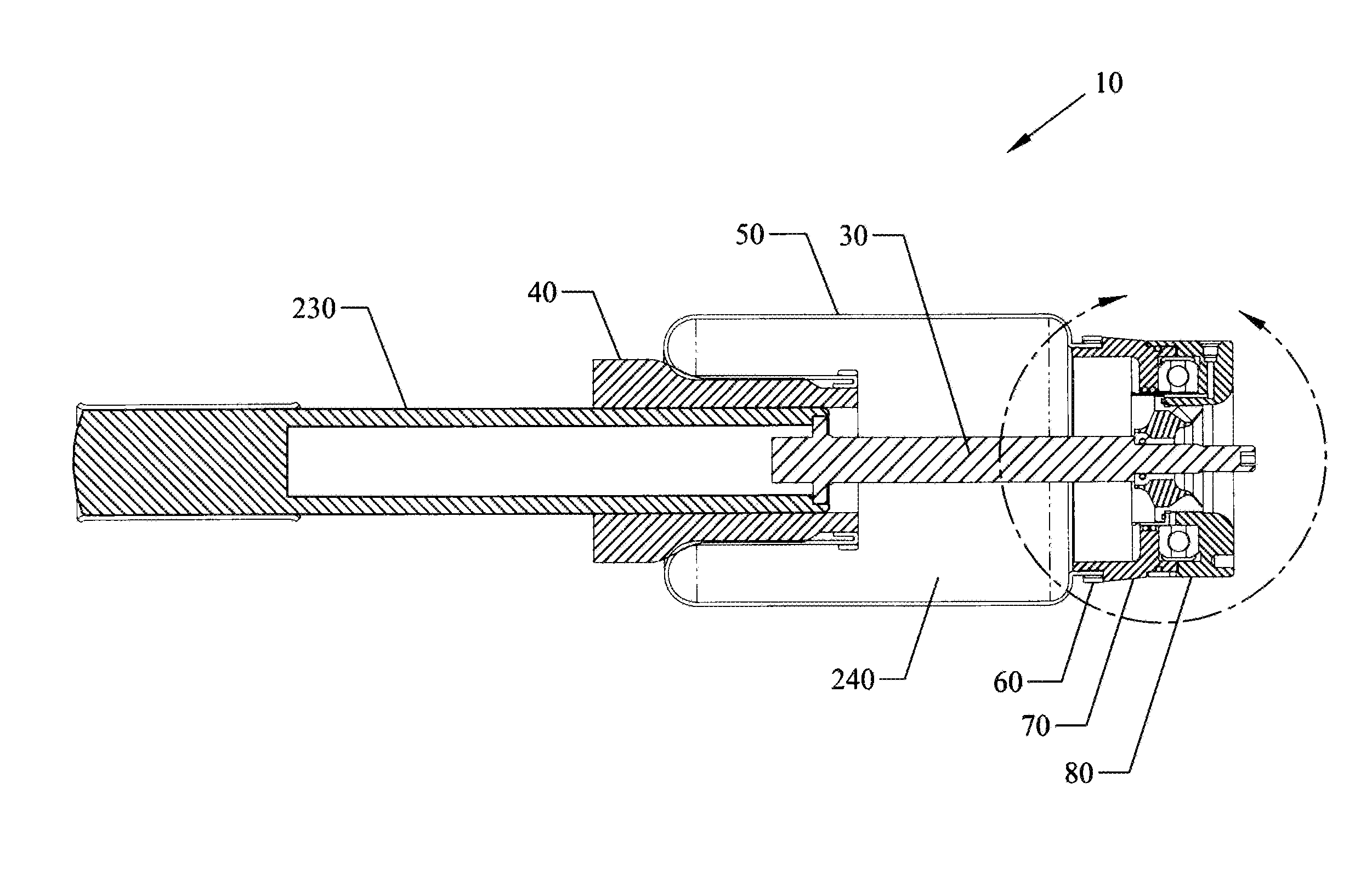
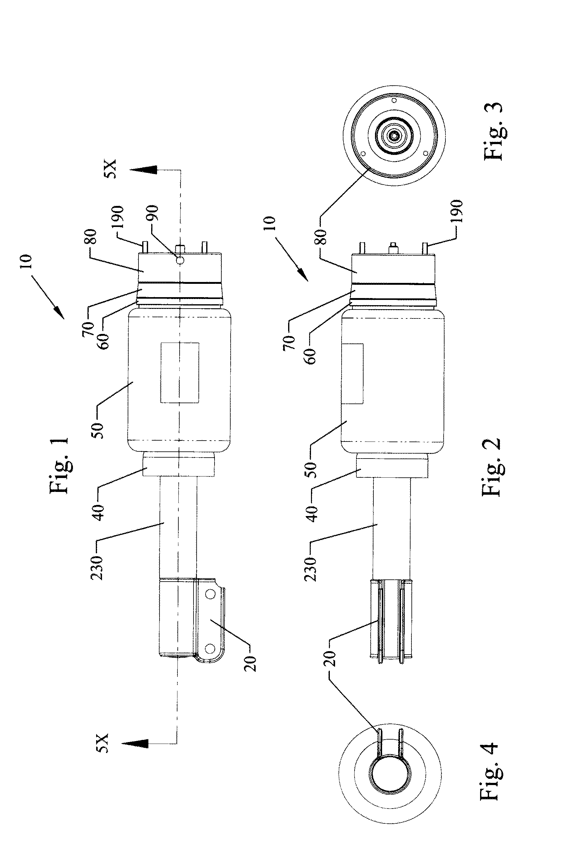
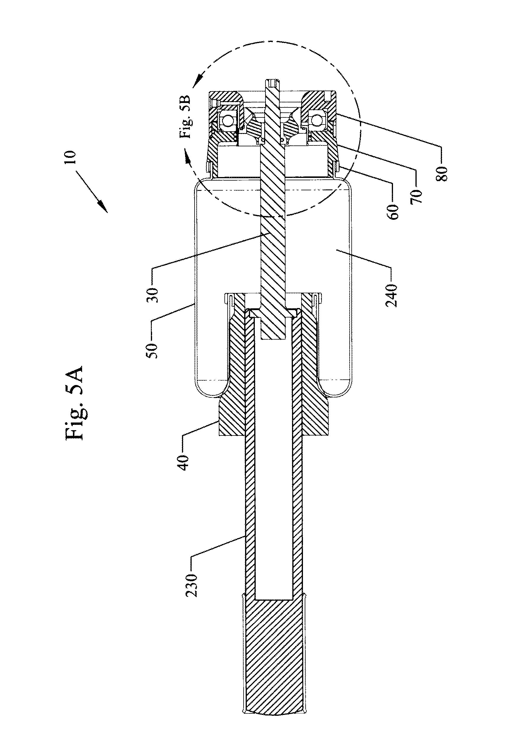
[0043]A list of the components will now be described.[0044]10. Air shock assembly of the invention[0045]10P. Prior art air shock assembly with external airline tube 200[0046]20. Mounting flange. Mounts shock to wheel.[0047]30. Internal shock[0048]40. Bottom piston[0049]50. Airbag[0050]60. Airbag crimp ring, large.[0051]70. Top (upper) mount piston[0052]72. Inner protruding piston end[0053]74. External upper side with groove for O-ring in upper piston 70[0054]80. Top (upper) mount. Mounts to vehicle chassis and does not rotate when the wheel turns.[0055]82. Inner top mount wall[0056]86. Lower end(lip) of top mount 80[0057]90. Air fit...


PUM


Abstract

Improved mount and bearing height adjustable air suspension shock absorber devices, apparatus, systems and methods, for use with sport utility vehicles(SUVs) such as Range Rovers®, and the like. Air lines run through an upper mount into an upper opening of an inflatable and deflatable airbag. The airlines have not external lines such as the nylon type tubing used in the prior art, and are not prone to failure which occurs more frequently with the external tubing air lines. Inflating and deflating the air springs/airbags (bladders) allows for the shock absorbers in the devices to be adjusted to different riding conditions over different types of terrains giving the rider a customized ride over different types of on road and off-road terrains. An internal air line machined into the head of the air suspension device provides a direct passageway for compressed air to pass into and out of the airbag without using external tubes. Sealing members such as O-rings provide airtight seals between the moving members of the head components of the air suspension devices.

Description

[0001]This invention relates to air suspension shocks, in particular to improved mount and bearing height adjustable air suspension shock absorber devices, apparatus, systems and methods, for sport utility vehicles(SUVs) such as Range Rovers®, and the like.BACKGROUND AND PRIOR ART[0002]Luxury sport utility vehicles(SUVs) such as the Range Rover® manufactured by the Land Rover Company in the United Kingdom, are known for comfortable rides in on and off-road ride applications. This has generally been achieved by four wheel independent height adjustable air suspension which allows for variable ride height for both on and off-road conditions. The driver can control the height adjustable suspension which is often used for traveling through rough riding terrain. The height adjustable air suspension systems are controlled by the driver running over rough terrain.[0003]These sophisticated types of air suspension systems can have numerous problems, such as air bag failure, air line failure, ...

Claims


Application Information

Patent Timeline
IPC IPC(8): B60G17/04
CPCB60G11/28B60G13/003B60G15/14B60G17/0521B60G2200/44B60G2500/30B60G2202/314B60G2204/128B60G2204/129B60G2204/418B60G2500/10B60G2202/152
Inventor ARNOTT, ADAM
Owner ARNOTT T&P HLDG LLC
Why Eureka
Try Eureka