
Infrared heating mechanism and system

a technology of infrared heating and heating mechanism, which is applied in the field of infrared heating mechanism and system, and can solve problems such as inefficiency

Inactive Publication Date: 2012-10-23
BROOKE SCOTT A +2
View PDF20 Cites 0 Cited by
  • Summary
  • Abstract
  • Description
  • Claims
  • Application Information

AI Technical Summary

Benefits of technology

[0011]In coordination with the wave length of the infrared bulb, substrate density and thickness, there is the proximity of the substrate material to the infrared bulb. The further distance that the substrate material is from the infrared light source, along with the actual light wave contact, the less actual energy particles from the light waves will make contact with the substrate material. If the substrate material is close and surrounds the light source 360 degrees, then all light wave particles will make contact with the substrate material and maximize the penetration.
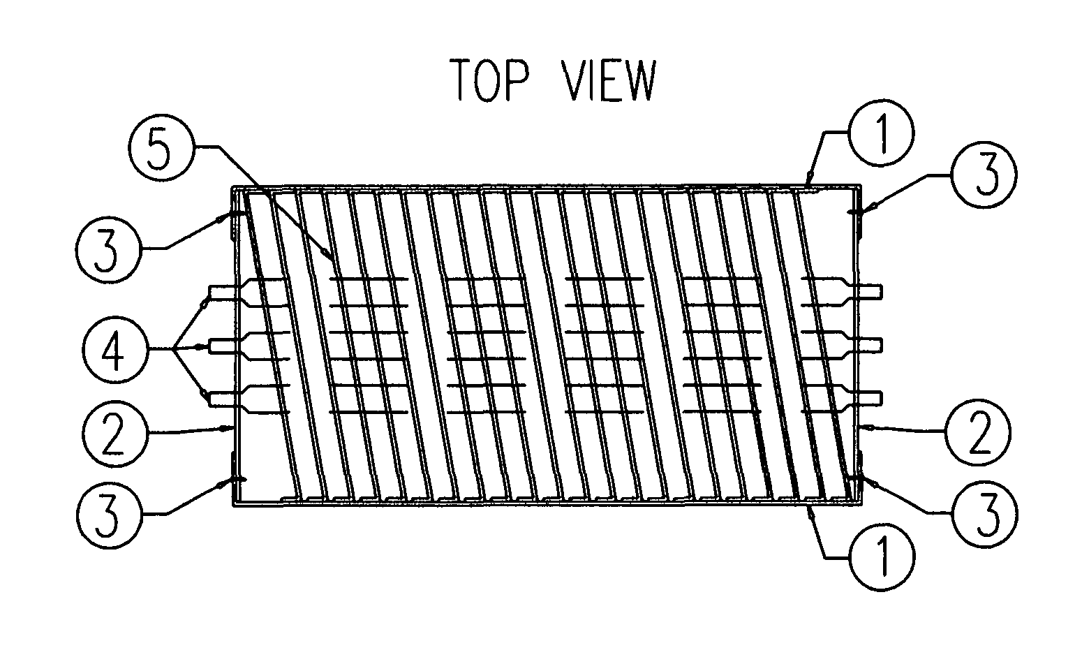
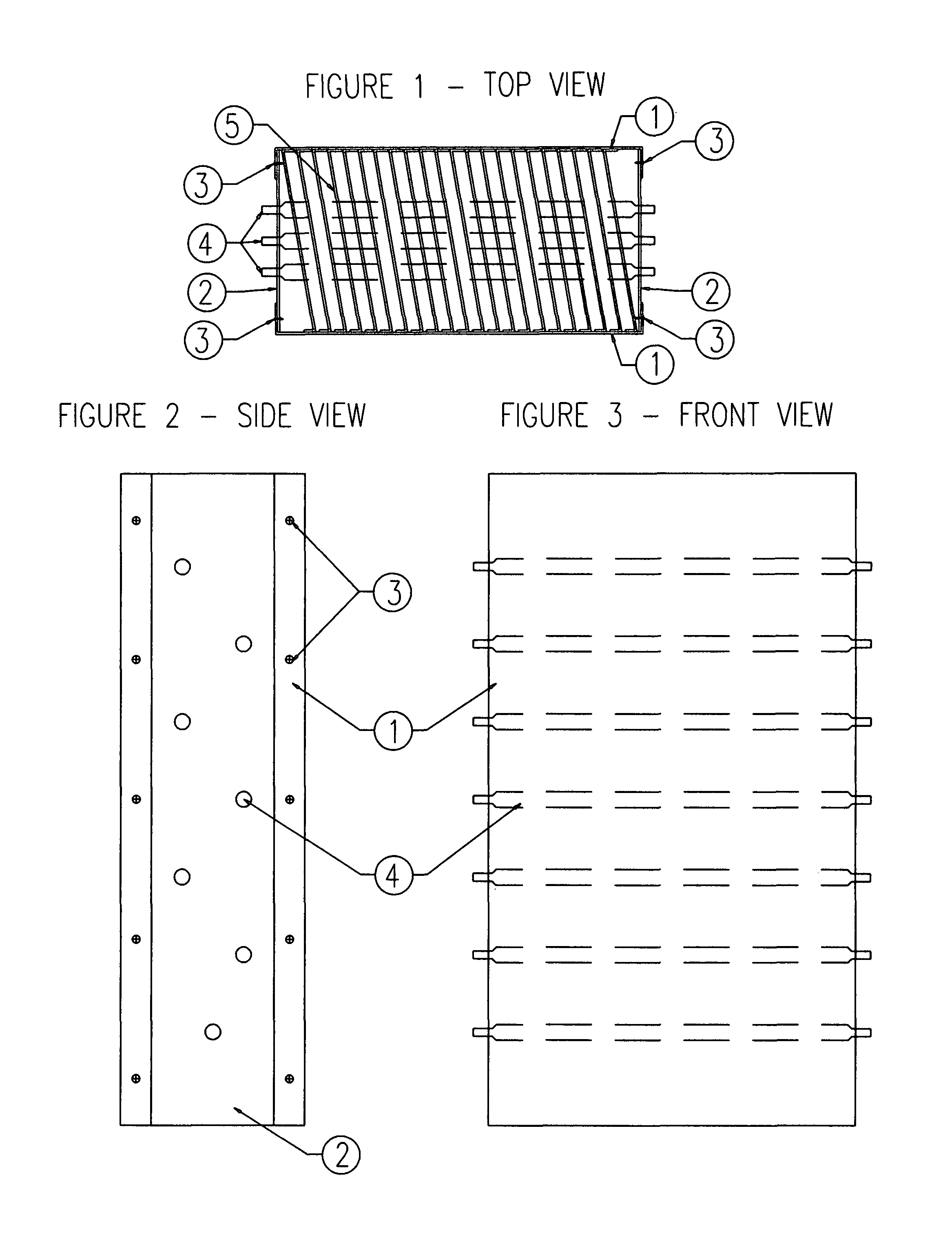
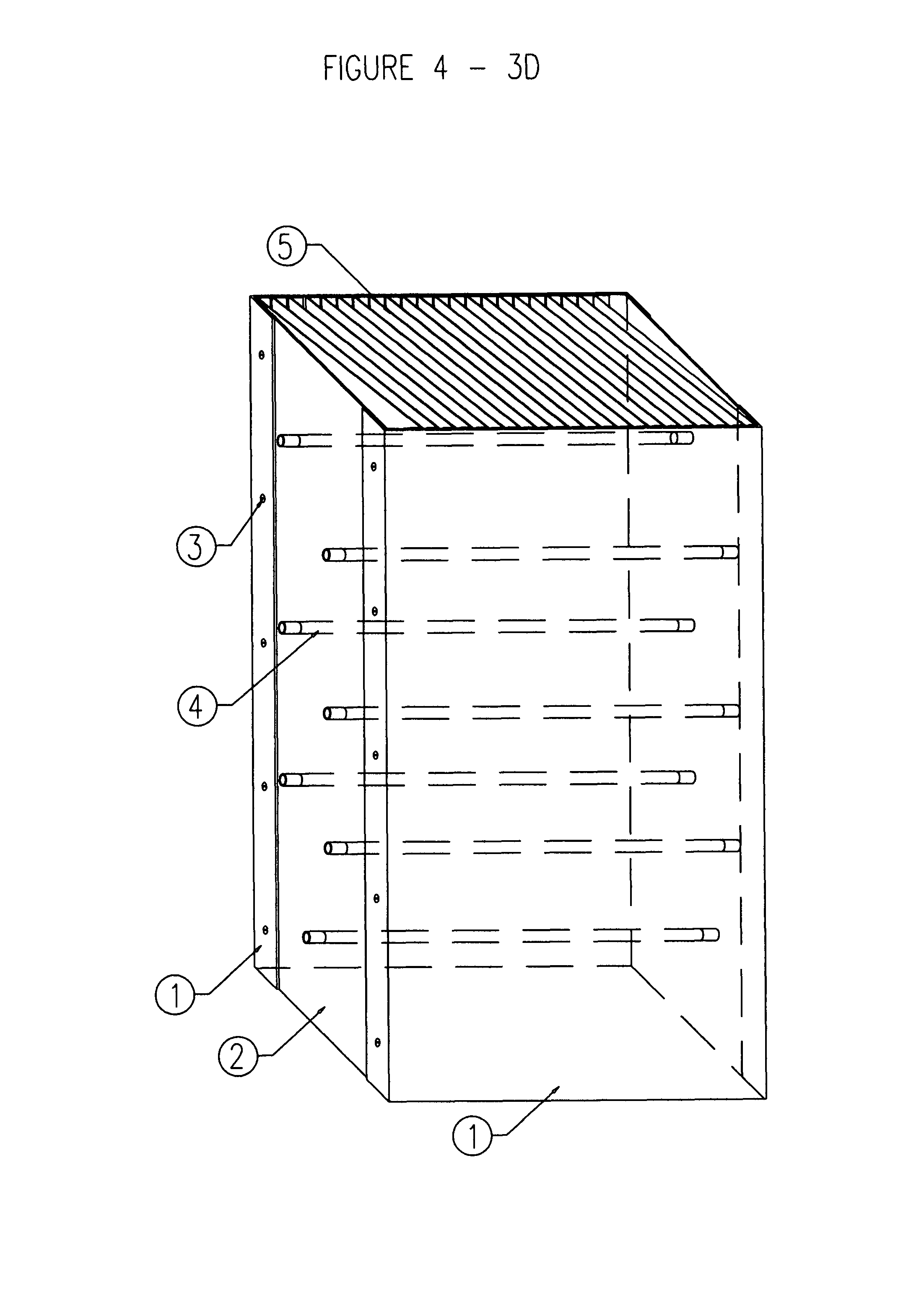
[0013]The bulbs are mounted in a housing that measures 6″ deep×21″ high×12″ wide with corners bent at a 90 degree angle and is made of aluminum with the interior finish being highly reflective. The polished interior of the aluminum housing reflects the infrared light waves back into the heat dissipation plates thus increasing the ability of the light waves to make visual contact with the dissipation plates. Furthermore, the polished interior minimizes the amount of energy penetration into the heater core housing and focuses the energy particles into the dissipation plates. At the base of the housing is mounted the fan of the appropriate size for the design. The fan is mounted into the base of the housing in a circular structure that is large enough to encompass the fan and motor unit. The fan housing attaches by self-tapping steel fasteners into the main heater core housing unit. The function of the fan is to bring in fresh air and force out the heated air from the heat exchange area of the heater core. See FIG. 6. The fan is mounted 3″ from the first heating element, in order to give an initial boost in ambient air temperature by immediately bringing input air into contact with the heating elements of the heater.
[0014]On the inside of the housing for the heater core are 22 carbon steel heat dissipation plates. Carbon steel has a molecular density that will allow deep penetration of the short wave particles and retain the heat energy. It is important to place as many plates as possible in the housing in order to maximize surface area of the dissipation plates to the light waves. The carbon steel plates are 4″ wide×21″ long×16 gauge thick and have 2, 2 inch crimped 10-degree angle flanges that are opposite each other and angled in opposite directions. See FIG. 5. From these crimped flanges the plates are mounted into the housing unit of the heater core with resistant welds. The plates are mounted into the heater core housing and are spaced ½″ apart from each plate and are configured in a parallel manner throughout the housing. See FIG. 4. The carbon steel plates are unpolished in order to maximize the amount of energy absorption from the short wave light bulbs. The reason that the heat dissipation plates are spaced at ½″ intervals is to maximize surface area and give 100% vision from the light bulbs. In each heat dissipation plate are seven (7) holes drilled to ½″ size and are spaced in a specific pattern. The holes in the heat dissipation plates will line up on each parallel dissipation plate that is mounted in the heater core housing. A single infrared light bulb will be mounted in each hole passing though each heat dissipation plate. The bulbs run perpendicular to the heat dissipation plates minus 10 degrees. See FIGS. 1-4. The position of the first infrared bulb in the heat dissipation plate will be in the center of the plates, 2″ from the edge of the heat dissipation plate, and will be located closest to the circulation fan. The hole is in the center to initiate even heat flow through the heater core housing. The remainder of the infrared light bulbs will be configured in a staggered pattern that starts at a 45-degree angle from the centered infrared light bulb. The bulbs are 2.5 inches away from each other through the remainder of the heat dissipation plates in the housing; this maximizes the light particle absorption of each infrared light bulb into the dissipation plate material.
[0015]The purpose of mounting the infrared light bulbs in this pattern and measurement is to maximize the coverage area that the infrared light bulbs can heat in the heat dissipation plates. The positioning of the bulbs (by angle and separation) through the dissipation plates maximizes the amount of surface area that the light bulbs make contact with thus increasing the amount of the surface area of the plates that will be heated.

Problems solved by technology

Other infrared heaters use outdated infrared bulb technology and do not position the bulbs and heat dissipation plates in a manner that captures the majority of infrared rays, thus not performing in an efficient manner.

Method used


Image

  • Infrared heating mechanism and system
  • Infrared heating mechanism and system
  • Infrared heating mechanism and system

Examples


Embodiment Construction

[0008]Infra-Wave Technologies, LLC has designed and developed a new heater core, called ECOWAVE 1.2, that utilizes a combination of infrared light bulbs, metal dissipation plates, thermostatic switches and blower fans in a precise configuration to achieve a 94-96 degree heat rise over ambient temperatures with a minimal electrical consumption of 3.083 KW per hour. Our heater core can produce an optimal rise in ambient temperature with no risk of explosion from volatile gas or heating oil, no risk of carbon monoxide poisoning and will operate at a temperature that is below the point where any material in the heated area of the heater core can combust. The heater core can be used in a multitude of configurations such as a stand-alone space heater, hanging bay heater, wall mounted heater, electric fireplace, and a retrofit unit (either single, direct duct or stacked) into an existing forced air system. See FIGS. 6-12.

[0009]The principal behind our Infra-Wave Technologies, LLC heater co...


PUM


Abstract

The ECOWAVE 1.2 is an infrared heater that can produce heat in a more efficient manner than other infrared heaters on the market today. We have utilized specific short wave infrared bulbs and specifically manufactured and oriented heat dissipation material, and housing, to capture the maximum amount of infrared waves emitted from the heat source thus providing an optimum ambient temperature rise for a minimal amount of electricity consumed. We have also designed a heater core, in two separate configurations, that can be used in a multitude of capacities depending on the size of the heating case desired, heat required and space available.

Description

BACKGROUND OF INVENTION[0001]Infra-Wave Technologies LLC derived an infrared based heater core that will operate to give an optimal rise in ambient temperature with a minimal amount of electrical consumption. We accomplish this by utilizing a short wave infrared bulb, in a specific configuration with specifically designed and oriented dissipation plates, that maximizes contact of the infrared waves with our uniquely designed and oriented heat dissipation plates. Other infrared heaters use outdated infrared bulb technology and do not position the bulbs and heat dissipation plates in a manner that captures the majority of infrared rays, thus not performing in an efficient manner. Our two designs for the heater core can be used in a multitude of configurations, either a single core placement or multiple core placements depending on the heat requirements. Other heaters on the market are only used in a specific heating scenario.BRIEF DESCPRIPTION OF THE DRAWINGS[0002]FIG. 1 is a sectiona...

Claims


Application Information

Patent Timeline
Patent Type & Authority Patents(United States)
IPC IPC(8): A45D20/40
CPCH05B3/008F24H3/0411
Inventor BROOKE, SCOTT A.REED, JEFF C.DOUGLAS, DONOVAN
Owner BROOKE SCOTT A
Learn More