
Membrane-electrode assembly and method for manufacturing the same

a technology of membrane electrolyte and assembly, which is applied in the direction of fuel cell details, cell components, electrochemical generators, etc., can solve the problems of chemical degradation of the polymer electrolyte membrane, the inability to meet the needs of customers, and the length of the process line, so as to achieve the effect of increasing the penetration of the electrolyte layer, improving physical and chemical durability and performance, and improving density

Active Publication Date: 2022-06-14
KOREA INST OF ENERGY RES
View PDF9 Cites 0 Cited by
  • Summary
  • Abstract
  • Description
  • Claims
  • Application Information

AI Technical Summary

Benefits of technology

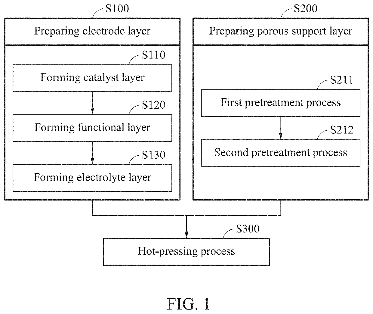
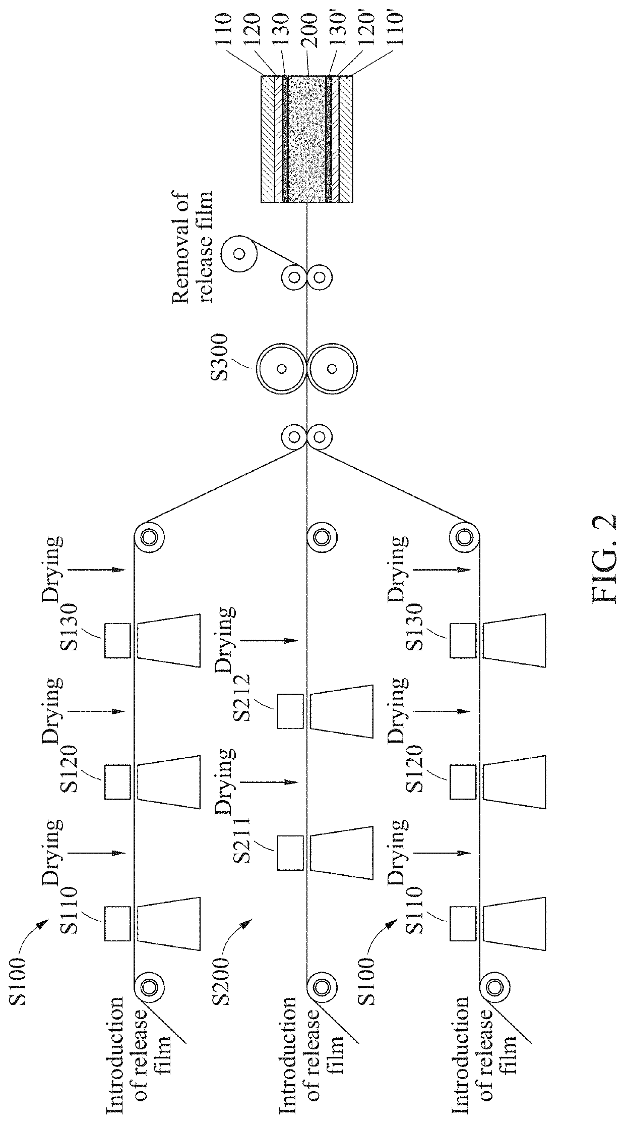
[0008]In order to solve the above-mentioned problems, an object of the present invention is to provide a method for manufacturing a membrane-electrode assembly, the method which improves physical and chemical durability of a membrane-electrode assembly, and reduces process line and improves continuity of the process by a hot-pressing process.
[0009]Another object of the present invention is to provide a membrane-electrode assembly which can improve performance of a fuel cell by applying a method for manufacturing a membrane-electrode assembly according to the present invention, thereby improving physical and chemical durability and minimizing interfacial resistance.
[0032]The present invention can provide an electrode layer (or an electrode) which can maximize penetration of the electrolyte layer with a porous support by forming a functional layer and an electrolyte layer on a catalyst layer (electrode), and a membrane-electrode assembly of which physical and chemical durability and performance are improved by a new hot-pressing process using a porous support with improved density.
[0033]The present invention facilitates standard adjustment of a membrane-electrode assembly, and can improve economic efficiency of manufacturing process by performing a continuous process, thereby reducing a process line and improving process efficiency.

Problems solved by technology

However, since the process requires a drying process in every step of coating an electrode and an electrolyte, there are problems that a line of the process is lengthened, and it is difficult to apply a standardized electrode catered to the needs of customers.
Chemical degradation of a polymer electrolyte membrane due to hydroxy radicals generated during operation of a fuel cell is a major issue in performance of a membrane-electrode assembly (MEA).
Particularly, when manufacturing the MEA from a perfluorinated sulfonic acid membrane of a short side chain having a high glass transition temperature and an aromatic hydrocarbon polymer by a hot pressing transfer method, higher temperature and pressure conditions are required, and interfacial stability of a completed product is deteriorated.
Further, a hot pressing transfer method of a high pressure may cause a mechanical defect fatal to a thin electrolyte membrane.
Interfacial stability is deteriorated also in a reinforced composite membrane of which the surface has hard characteristics when manufacturing the MEA by the decal process.
Such manufactured MEA has a problem that performance of the fuel cell is reduced sharply as a detachment phenomenon between an electrolyte membrane and an electrode is occurred, and durability is deteriorated during operation of a fuel cell.
Although an MEA manufacturing process including a reinforced composite membrane has recently been developed by a continuous coating method, as a drying process is required in every coating step, there is a problem that a line of the process is lengthened, and there is a demerit that it is difficult to standardize size of an electrode in accordance with customers' needs.

Method used


Image

  • Membrane-electrode assembly and method for manufacturing the same
  • Membrane-electrode assembly and method for manufacturing the same
  • Membrane-electrode assembly and method for manufacturing the same

Examples


example 1

acturing-Alcohol Based Support Pretreatment Solution Including a Perfluorinated Reinforced Composite Membrane

[0117]Manufacturing of a Functional Layer Coated Electrode

[0118]According to configuration of the following table 1, a catalyst layer coating composition was prepared by using a carbon-supported platinum catalyst (Pt / C), and a solution including Aquivion resin (Aquivion D83), i.e., an aprotic solvent (N-methyl-2-pyrrolidone, NMP)-based hydrogen ion conductive binder. The catalyst layer coating composition comprises 35 wt % of Aquivion ionomer with respect to the total solid.

[0119]

TABLE 1ComponentsPt / CAquivion solidNMPWt %6.53.590

[0120]10 wt % of a functional layer coating composition was prepared by adding 5 wt % of hexane-1-ol alcohol to an Aquivion resin (Aquivion D83) suspension including 76 wt % of water, i.e., a hydrogen ion conductive binder, adding 2.5 mol % of cerium (III) ions (an antioxidant) and 1 mol % of platinum-supported carbon particles (a gas permeation reduc...

example 2

acturing-Nonaqueous Support Pretreatment Solution Including a Perfluorinated Reinforced Composite Membrane

[0128]Pretreatment of a Polytetrafluoroethylene Porous Support

[0129]After dipping a porous polytetrafluoroethylene (PTFE) support in ethanol for 30 minutes, impurities inside pores of the PTFE support were removed by vacuum-drying the PTFE support at 50° C.

[0130]After substituting solvent of an Aquivion resin (Aquivion D83) suspension containing 76 wt % of water by N-methyl-2-pyrrolidone (NMP) as an aprotic solvent, 2 wt % of a nonaqueous solution composition was prepared by adding 0.4 wt % of 2-(perfluorohexyl)ethanol as an impregnation accelerator to the solvent-substituted suspension. The PTFE support was moisturized by dipping the PTFE support in the prepared solution composition for 10 minutes.

[0131]Manufacturing of a Membrane-Electrode Assembly

[0132]An MEA was manufactured through a roll lamination process having the same conditions as in Example 1 by using a functional la...

example 3

acturing-Nonaqueous Support Pretreatment Solution Including a Hydrocarbon-Based Reinforced Composite Membrane

[0133]Pretreatment of a Polyethylene Porous Support

[0134]After dipping a porous polyethylene (PE) support in ethanol for 30 minutes, impurities inside pores of the PE support were removed by vacuum-drying the PE support at 50° C.

[0135]After dissolving sulfonated poly(arylene ether sulfone) (SPES 50) having a degree of sulfonation of 50% as a commercial hydrocarbon polymer into N-methyl-2-pyrrolidone (NMP) as an aprotic solvent, 2 wt % of a solution composition was prepared by adding 0.4 wt % of 2-(perfluorohexyl)ethanol as an impregnation accelerator to the commercial hydrocarbon polymer dissolved with the aprotic solvent. The PE support was moisturized by dipping the PE support in the prepared solution composition for 10 minutes.

[0136]Manufacturing of a Membrane-Electrode Assembly

[0137]An MEA was manufactured through a roll lamination process having the same conditions as in...


PUM

PropertyMeasurementUnit
temperatureaaaaaaaaaa
thicknessaaaaaaaaaa
speedaaaaaaaaaa

Abstract

Provided is a method for manufacturing a membrane-electrode assembly. The method includes forming an electrode layer, preparing a porous support layer, and positioning the electrode layer on each of both surfaces of the porous support layer and hot-pressing the electrode layer positioned on the both surfaces. The forming of the electrode layer incudes forming a functional layer including a hydrogen ion conductive binder resin on at least a portion of an electrode catalyst layer, and forming an electrolyte layer on at least a portion of the functional layer. The preparing of the porous support layer includes performing a pretreatment process by impregnating the porous support layer with a pretreatment composition, and the performing of the pretreatment process includes dipping the porous support layer in a first pretreatment composition and then drying the porous support layer, and dipping the porous support layer after drying in a second pretreatment composition.

Description

CROSS-REFERENCE TO RELATED APPLICATION(S)[0001]This application claims the benefit of Korean Patent Application No. 10-2019-0150667 filed on Nov. 21, 2019, in the Korean Intellectual Property Office, the disclosure of which is incorporated herein by reference.BACKGROUND1. Field of the Invention[0002]The present invention relates to a method for manufacturing a membrane-electrode assembly, a membrane-electrode assembly, and a fuel cell.2. Description of the Related Art[0003]A membrane-electrode assembly including a polymer electrolyte membrane and an electrode is a core component having an effect on performance and durability of a polymer electrolyte fuel cell. The polymer electrolyte membrane from the components most typically includes a perfluorinated polymer electrolyte membrane such as Nafion® membrane manufactured by Dupont Corporation and Aquivion® membrane manufactured by Solvay Corporation, and research of developing a hydrocarbon polymer electrolyte membrane for replacing an...

Claims


Application Information

Patent Timeline
Patent Type & Authority Patents(United States)
IPC IPC(8): H01M8/10H01M8/1004H01M4/86
CPCH01M8/1004H01M4/8668H01M2008/1095H01M4/8605H01M4/8663H01M4/8673H01M8/1058H01M8/1069H01M4/8636H01M8/023H01M8/0239
Inventor SHIN, SUNG HEEBAE, BYUNG CHANPARK, SEOK HEEKIM, CHANG SOOLEE, WON YONGPARK, GU GONYANG, TAE HYUNYIM, SUNG DAEKIM, MIN JINSOHN, YOUNG JUNKIM, SEUNG GONSHIN, DONG WONOH, HWAN YEONGLEE, HYE JIN
Owner KOREA INST OF ENERGY RES
Learn More