
WiFi peripheral mode

a peripheral mode and wireless technology, applied in the field of wireless peripheral mode, can solve the problems of increasing the minimum processing capability needed by each mesh device, adding conventional mesh capability to peripherals, and in particular low-cost battery-based peripherals, and achieves enhanced wireless peripheral mode, facilitate optimal system interoperability and functionality, and effectively and efficiently implement

Active Publication Date: 2012-10-23
III HLDG 1
View PDF8 Cites 16 Cited by
  • Summary
  • Abstract
  • Description
  • Claims
  • Application Information

AI Technical Summary

Benefits of technology

[0014]Therefore, the present invention effectively implements a flexible wireless system that utilizes various heterogeneous components to facilitate optimal system interoperability and functionality. The present invention thus effectively and efficiently implements an enhanced wireless peripheral mode.

Problems solved by technology

Developing effective methods for operating wireless electronic peripherals is a significant challenge for modern system designers.
This adds cost to the computer system and if, as is typical, the computer does not integrate the RF chips for peripheral devices, requires the use of an external dongle.
One downside of mesh networking is that it increases the minimum processing capability needed by each mesh device.
While add mesh capability typically would not be a problem for a computer, adding conventional mesh capability for peripherals and in particular for low cost battery based peripherals is a large burden.
For low bandwidth low cost peripherals it is not desirable to either add additional RF channels or increase the complexity of the WiFi features.
However, standard WiFi does not support a host system that can concurrently operate a single WiFi channel for both infrastructure mode and peripheral support.

Method used


Image

  • WiFi peripheral mode
  • WiFi peripheral mode
  • WiFi peripheral mode

Examples


Embodiment Construction

[0020]The present invention relates to an improvement for a wireless peripheral system. While the described embodiments relate to a host computer system, the same principles and features could be equally applied to host cell phone, host MP3 player and host media system.

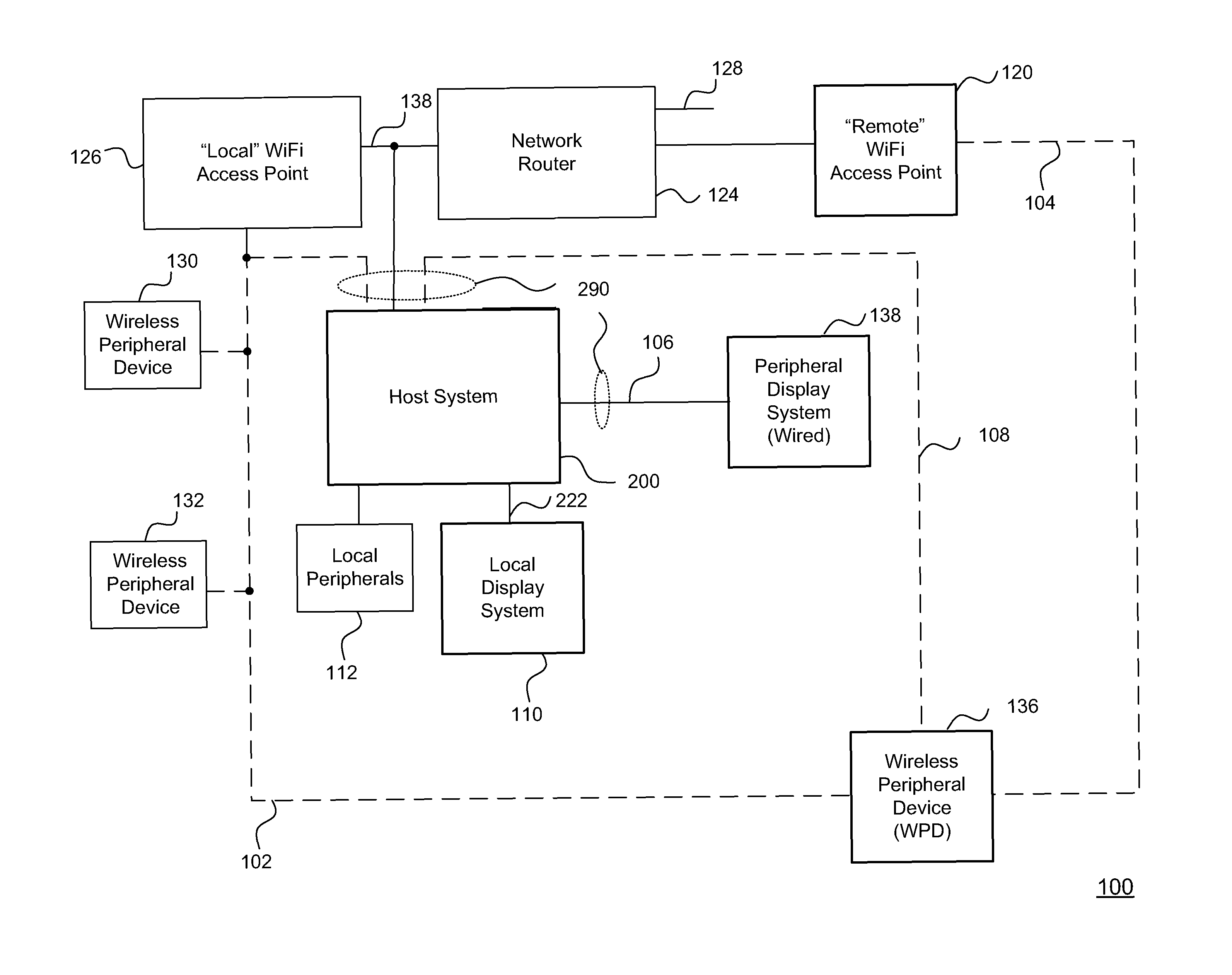
[0021]Referring to FIG. 1, the invention provides an architecture for a wireless peripheral system 100 to make use of wireless peripherals 130, 132 and 136. A host system 200 may be connected via a wired connection 138 to a network 128 or may be part of a wireless network 102. A wired network 128 may be a conventional wired Ethernet network or another wire technology such as COAX or power line. In any of those cases, the network interface of host system 200 is managed by a Physical (PHY) interface as well as a network controller that is capable of supporting the protocols associated with the physical interface. In addition to or instead of a wired network interface, the host system 200 may be part of a wireless networ...


PUM


Abstract

A wireless peripheral mode is provided by a host system that communicates to a WiFi infrastructure and, utilizing the same WiFi RF subsystem, also communicates to peripherals. The host system may employ additional RF channels for communicating with high bandwidth peripherals, such as display devices, where high levels of QoS may be managed locally. The host system may be a conventional desktop computer system, a notebook computer system, a multi-media access point, a cell phone, a game machine, a portable game machine, a Personal Digital Assistant (PDA), a smart phone or any other type of device that benefits from accessing both a WiFi infrastructure and local peripherals.

Description

[0001]This application is a Continuation of U.S. application Ser. No. 11 / 230,872 filed Sep. 19, 2005 now U.S. Pat. No. 8,019,883 which claims the benefit of U.S. Provisional Application No. 60 / 705,153 filed Aug. 4, 2005 and which is a Continuation-in-Part of U.S. application Ser. No. 11 / 122,457 filed May 5, 2005 now U.S. Pat. No. 7,667,707 and of U.S. application Ser. No. 11 / 139,149 filed May 27, 2005.BACKGROUND OF THE INVENTION[0002]1. Field of the Invention[0003]The present invention relates generally to a computer system for wirelessly connecting peripheral devices and more particularly to methods for wirelessly connecting a host computer to supporting WiFi peripherals and for wirelessly supporting additional display systems.[0004]2. Description of the Background Art[0005]In recent years, there has been growing popularity for the WiFi standard for wireless communication. WiFi is a collection of standards of which the main standards are 802.11g (which incorporates 802.11b) and 802...

Claims


Application Information

Patent Timeline
Patent Type & Authority Patents(United States)
IPC IPC(8): G06F15/16
CPCG06F1/266G06F1/325G06F3/1431G06F3/1438G06F3/1446H04N5/44591H04N21/4122H04N21/440218H04N21/4126H04N21/42653H04N21/43637H04W84/18G06F3/1454H04L5/0037H04L65/60G06F1/3203H04L65/608H04L65/4069H04N21/47H04N21/4316H04N21/41265H04L65/61H04L65/65G06T11/60G06T15/005G06T19/20H04W84/12
Inventor MARGULIS, NEAL D.
Owner III HLDG 1
Learn More