Method for making surveillance devices with multiple capacitors

a technology of surveillance devices and capacitors, applied in the direction of fixed capacitor details, paper/cardboard articles, instruments, etc., can solve the problems of difficult to fabricate capacitors with very small dimensions with high precision, and achieve high precision capacitance, low breakdown voltage, and relatively reliable tag deactivation

Active Publication Date: 2012-10-30
ENSURGE MICROPOWER ASA
View PDF11 Cites 6 Cited by
  • Summary
  • Abstract
  • Description
  • Claims
  • Application Information

AI Technical Summary

Benefits of technology

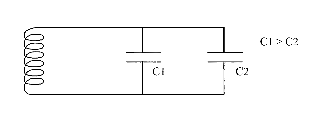
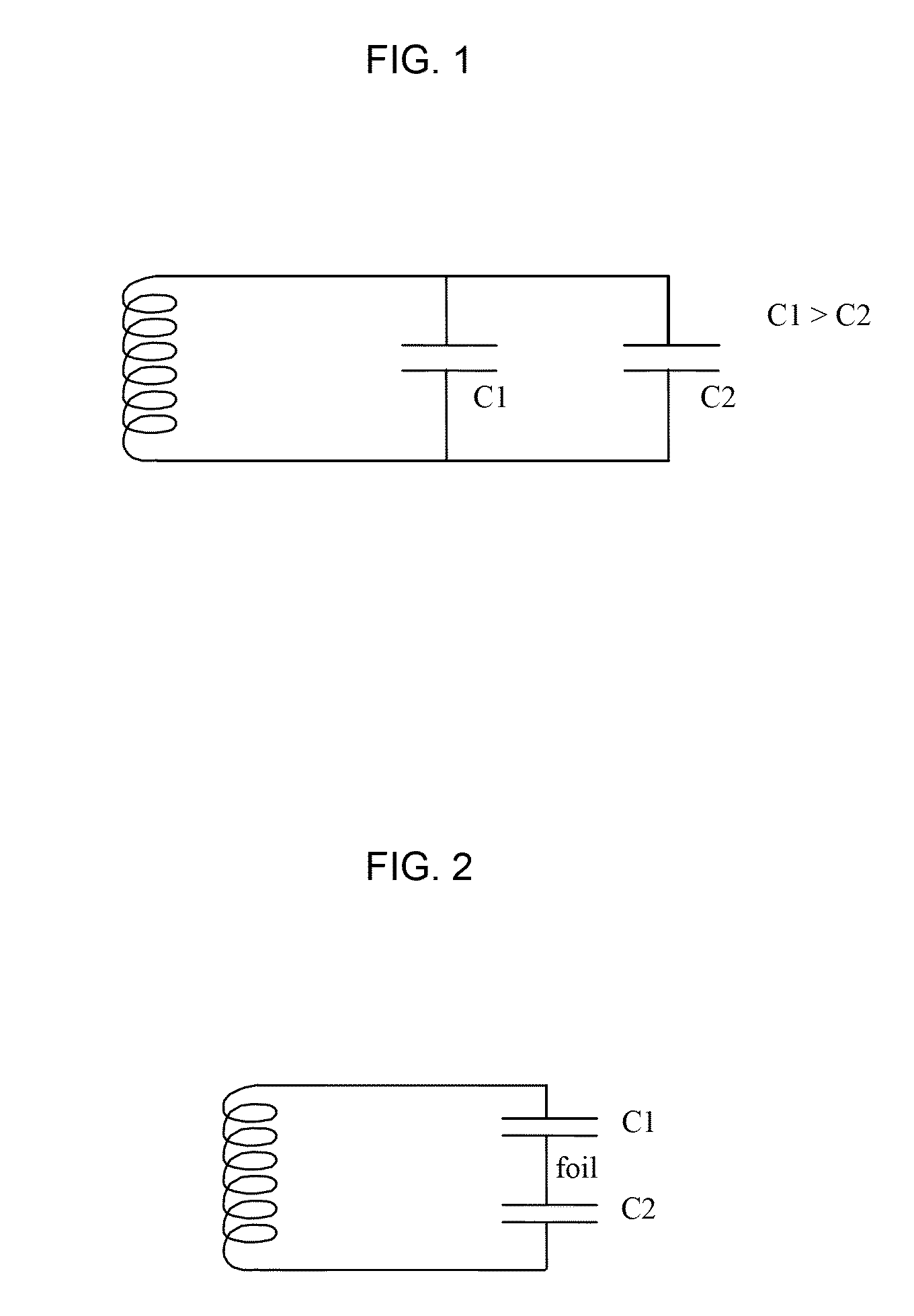
[0005]A first aspect of the present invention concerns methods of making surveillance and / or identification devices having multiple capacitors. In some embodiments, the capacitors may be connected in parallel. Making a device with capacitors in parallel may achieve both a high-precision capacitance and a low breakdown voltage for easy surveillance tag deactivation. For example, in embodiments of the present invention, the single capacitor generally used in surveillance and / or identification devices is replaced with a plurality of capacitors, which are connected in parallel. In other embodiments, the capacitors may be connected in series. Making a device with capacitors in series effectively increases the lateral dimensions of a small capacitor. This configuration makes the capacitor easier to manufacture using techniques that may have relatively limited resolution capabilities. For example, in embodiments of the present invention, the single capacitor generally used in surveillance and / or identification devices is replaced with a plurality of capacitors, which are connected in series.
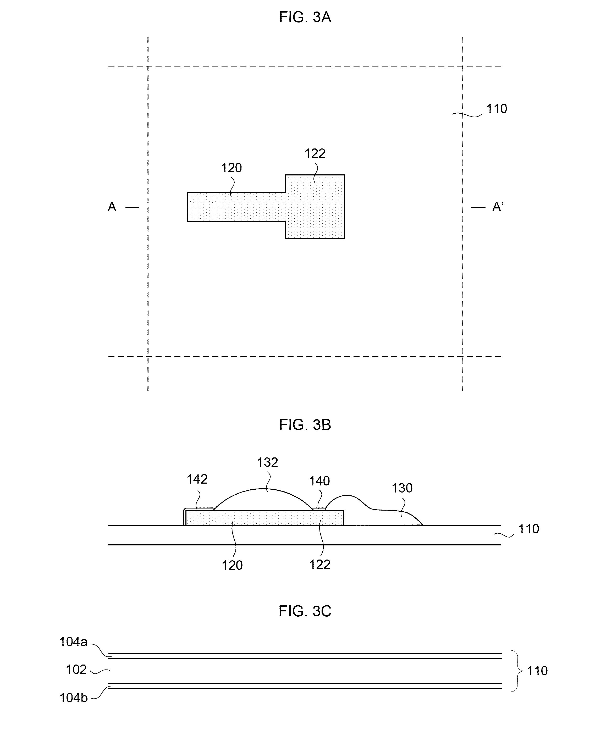
[0007]In exemplary embodiments for making a device with parallel capacitors, the electrically conducting strap and the lower capacitor electrode are formed in a single processing sequence (e.g., by printing), and the lower capacitor electrode is shared by the parallel capacitors. Printing processes may be preferred over conventional blanket deposition, photolithography and etching processes, because printing reduces the number of processing steps, the length of time for the manufacturing process, and / or the cost of materials used to manufacture the capacitor and / or surveillance / identification device.
[0008]In a second exemplary embodiment, a wireless surveillance and / or identification device with parallel capacitors can be made by (a) forming an antenna and / or inductor on a substrate and a lower capacitor electrode in electrical communication with a first end of the antenna / inductor; (b) forming a relatively thin capacitor dielectric film on at least a first part of the lower capacitor electrode; (c) forming a relatively thick capacitor dielectric on or over a second part of the lower capacitor electrode, the second part of the lower capacitor electrode not overlapping with the first part thereof; (d) forming an upper capacitor electrode on the thin and thick capacitor dielectric films, capacitively coupled to the lower capacitor electrode; and (e) forming an electrically conducting strap configured to provide electrical communication between the upper capacitor electrode and a second end of the antenna / inductor. Forming the structures and / or layers of the device in such an arrangement (e.g., forming a lower capacitor electrode, the relatively thin and the relatively thick capacitor dielectric films, and an upper capacitor electrode), allows for the formation of parallel capacitors with dielectric film of different thicknesses under controlled and reproducible conditions using the same sequence of steps, and in the case of printing, without photolithography.
[0014]The embodiments described herein provide surveillance tags and / or devices having high-precision capacitance and a low breakdown voltage to provide relatively reliable tag deactivation and / or high precision printing of capacitors having very small dimension(s). These and other advantages of the present invention will become readily apparent from the detailed description of preferred embodiments below.

Problems solved by technology

Fabricating a capacitor with both a low breakdown voltage, and thus, a relatively thin dielectric, while achieving high precision capacitance can be difficult.
In addition, it is difficult to fabricate a capacitor having very small dimensions with high precision.

Method used


Image

  • Method for making surveillance devices with multiple capacitors
  • Method for making surveillance devices with multiple capacitors
  • Method for making surveillance devices with multiple capacitors

Examples


Embodiment Construction

[0033]Reference will now be made in detail to embodiments of the present invention, examples of which are illustrated in the accompanying drawings. While the invention will be described in conjunction with various embodiments, it will be understood that they are not intended to limit the invention to these embodiments. On the contrary, the invention is intended to cover alternatives, modifications and equivalents, which may be included within the scope of the invention as defined by the appended claims. Furthermore, in the following detailed description of the present invention, numerous specific details are set forth in order to provide a thorough understanding of the present invention. However, it will be readily apparent to one skilled in the art that the present invention may be practiced without these specific details. In other instances, well-known methods, procedures, components, and circuits have not been described in detail so as not to unnecessarily obscure aspects of the ...


PUM

PropertyMeasurementUnit
thicknessaaaaaaaaaa
thicknessaaaaaaaaaa
thicknessaaaaaaaaaa

Abstract

The present invention relates to surveillance and / or identification devices having capacitors connected in parallel or in series, and methods of making and using such devices. Devices with capacitors connected in parallel, where one capacitor is fabricated with a relatively thick capacitor dielectric and another is fabricated with a relatively thin capacitor dielectric achieve both a high-precision capacitance and a low breakdown voltage for relatively easy surveillance tag deactivation. Devices with capacitors connected in series result in increased lateral dimensions of a small capacitor. This makes the capacitor easier to fabricate using techniques that may have relatively limited resolution capabilities.

Description

RELATED APPLICATIONS[0001]This application claims the benefit of U.S. Provisional Application Nos. 61 / 127,899 and 61 / 056,804, respectively filed on May 15, 2008 and May 28, 2008, each of which is incorporated herein by reference in its entirety.FIELD OF THE INVENTION[0002]The present invention generally relates to the field of surveillance and / or identification tags and devices. More specifically, embodiments of the present invention pertain to wireless (e.g., EAS, RF, RFID, HF, VHF, UHF, etc.) tags / devices having multiple capacitors connected in parallel or series, structures and methods for their manufacturing and / or production, and methods of using such tags and / or devices.BACKGROUND[0003]Surveillance devices, such as Electronic Article Surveillance (EAS) devices or tags, are typically fabricated with a capacitor and / or diode, which are permanently altered to de-tune or deactivate the surveillance device. Fabricating a capacitor with both a low breakdown voltage, and thus, a rela...

Claims


Application Information

Patent Timeline
Patent Type & Authority Patents(United States)
IPC IPC(8): H05K3/02H05K3/10
CPCG08B13/2414G08B13/242G08B13/2431G08B13/2437G08B13/2442H01G4/18Y10T29/435Y10T29/413Y10T29/49155Y10T29/49016Y10T29/49128B31D1/025G06K19/07783G06K19/07798
Inventor SMITH, PATRICKCHOI, CRISWELLCLEEVES, JAMES MONTAGUESUBRAMANIAN, VIVEKKAMATH, ARVINDMOLESA, STEVEN
Owner ENSURGE MICROPOWER ASA
Why Eureka
Try Eureka