Microtesting rig with variable compliance loading fibers for measuring mechanical properties of small specimens

a micro-testing rig and loading fiber technology, which is applied in the direction of instruments, material strength using tensile/compressive forces, and withdrawing sample devices, etc., can solve the problems that ex-situ micro-scale tests are affected by some of the same undesired influences, and achieves control of lateral stiffness, and high stiffness conditions

Active Publication Date: 2012-10-30
US SEC THE AIR FORCE THE
View PDF4 Cites 7 Cited by
  • Summary
  • Abstract
  • Description
  • Claims
  • Application Information

AI Technical Summary

Benefits of technology

[0008]The present invention provides a device designed and constructed to allow the quantitative measurement of deformation properties in micron-sized specimens while imparting an exceedingly small constraining force to the deforming body. Ex-situ test methodologies can provide high precision data that relate quantitative stress and strain response during deformation. The present invention provides an alternative in-situ testing approach that also employs simultaneous electron imaging of very small test specimens within a scanning electron microscope (SEM) or dual beam focused ion beam (DBFIB) during the deformation experiment. These images are used to correlate the stress-strain data with the spatial and temporal nature of deformation-induced flow and fracture events that develop during the course of a test. Real time imaging facilitates the operation of tests on micro-samples that rely on complex set-ups, such as the alignment of tension grips about very small free-standing specimens.
[0009]The present invention incorporates a high precision piezoelectric actuator, a high precision inertial force positioning stage, a small, low profile load cell and a variety of highly compliant contact platens and grips that can be manufactured from a SiC or similar compliant fiber. Displacement along the specimen gauge length is measured directly from the images. Both compression and tension experiments have been conducted on microsized samples fabricated from bulk material using the DBFIS. These specimens are fabricated to elicit the simple stress states afforded by uniaxial loading of standard geometric shapes (e.g. round pillars, rectangular “dog bone” plates, etc.).
[0012]Construction of the microtesting rig in the invention offers certain advantages over the current technology available for microscale mechanical testing. While the lateral stiffness in nanoindenter systems is fixed at some intermediate value, they are not specifically designed to be excessively stiff. This methodology also currently employs only diamond contact tips, which are intrinsically very stiff. Thus, lateral contact stiffness in these systems is limited to the intermediate lateral stiffness intrinsic to the load train into which the diamond is mounted. The high-end lateral stiffness, for the present invention, is much greater at 0.1 N / μm. This enables microscale mechanical testing under new, higher stiffness conditions.
[0013]The fiber can be used to control the lateral stiffness for microscale testing. Fibers of varying length, diameter, and composition can be used to affect the properties in the fiber contact and thereby control lateral stiffness at the sample / fiber contact. This enables microscale mechanical testing under new, ultra-low stiffness conditions.
[0014]The concept of variable contact tips possessing different properties is new and allows a range of imposed lateral stiffness conditions for an experiment. The device in this invention begins with a high natural system stiffness, by design, and thus offers a wide range in potential lateral stiffness during testing.

Problems solved by technology

These ex-situ micro-scale tests are affected by some of the same undesired influences as experienced in bulk compression tests.

Method used


Image

  • Microtesting rig with variable compliance loading fibers for measuring mechanical properties of small specimens
  • Microtesting rig with variable compliance loading fibers for measuring mechanical properties of small specimens
  • Microtesting rig with variable compliance loading fibers for measuring mechanical properties of small specimens

Examples


Embodiment Construction

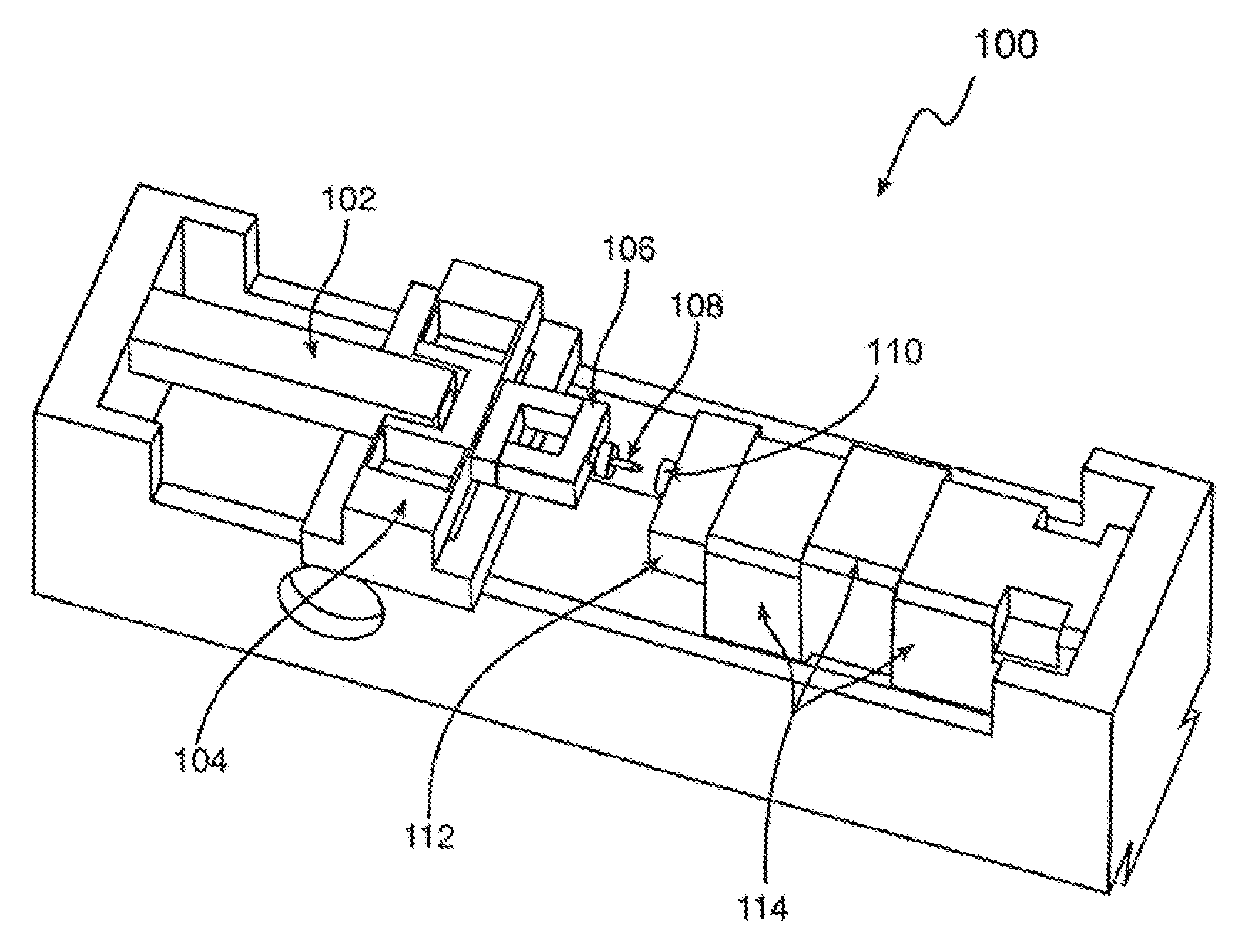
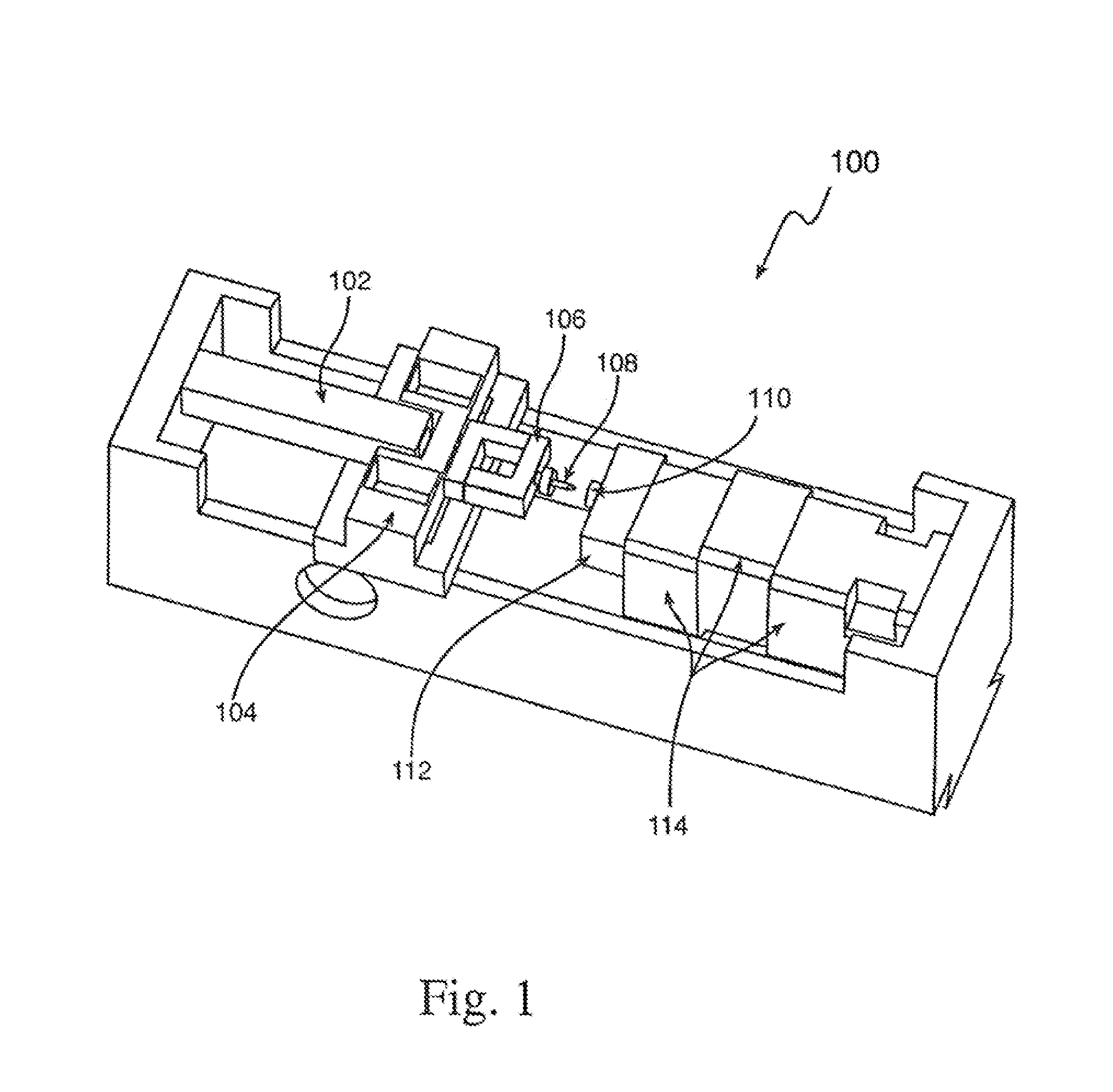
[0024]utilizes a compliant fiber within an existing testing frame used to investigate deformation behavior of microsized specimens. Initially, compression tests were conducted using the test system equipped with a diamond platen (without a compliant fiber). Test results differed from ex-situ results conducted using a nanoindenter. It was contemplated that lateral stiffness in the system was the likely source of these differences. This problem was overcome by the use of a fiber to allow testing of appropriately fabricated samples in tension. A fixed grip was designed and cut into the free end of a fiber using the focused ion beam microscope. A compliant SiC fiber was chosen, which would allow for minor self alignment of the grip during initial application of load to the microsamples and would accommodate lateral movements induced by deforming specimens. The SiC fiber was chosen for the grip application because of the high stiffness along its length and low stiffness perpendicular to ...


PUM


Abstract

The present invention provides a microtesting rig for measuring mechanical properties of small specimens. The rig includes a microsized specimen positioned on a mounting block, an interchangeable contact tip connected with an actuator and configured for contact with the microsized specimen, and a magnifying imaging system for imaging the microsized specimen. The contact tip may be a fiber platen for compression testing or a fiber grip for tension testing.

Description

CROSS-REFERENCE TO RELATED APPLICATION[0001]The present application relates to and claims priority to U.S. Provisional Patent Application No. 61 / 113,735 filed Nov. 12, 2008. The contents of U.S. Provisional Patent Application No. 61 / 113,735 are hereby incorporated by reference.RIGHTS OF THE GOVERNMENT[0002]The invention described herein may be manufactured and used by or for the Government of the United States for all governmental purposes without the payment of any royalty.FIELD OF THE INVENTION[0003]The present invention relates generally to an improved mechanism that enables quantitative mechanical testing of microsized samples by introducing variable lateral constraints imposed by the lateral stiffness of the testing device. More particularly, the invention employs a flexible fiber or other highly compliant structure that can support a contacting tip for both tensile and compressive test modes.BACKGROUND OF THE INVENTION[0004]The measurement of mechanical behavior in very small ...

Claims


Application Information

Patent Timeline
Patent Type & Authority Patents(United States)
IPC IPC(8): G01N3/08
CPCG01N1/2226G01N1/24
Inventor WHEELER, IV, ROBERTSHADE, PAUL A.UCHIC, MICHAEL D.
Owner US SEC THE AIR FORCE THE
Why Eureka
Try Eureka