
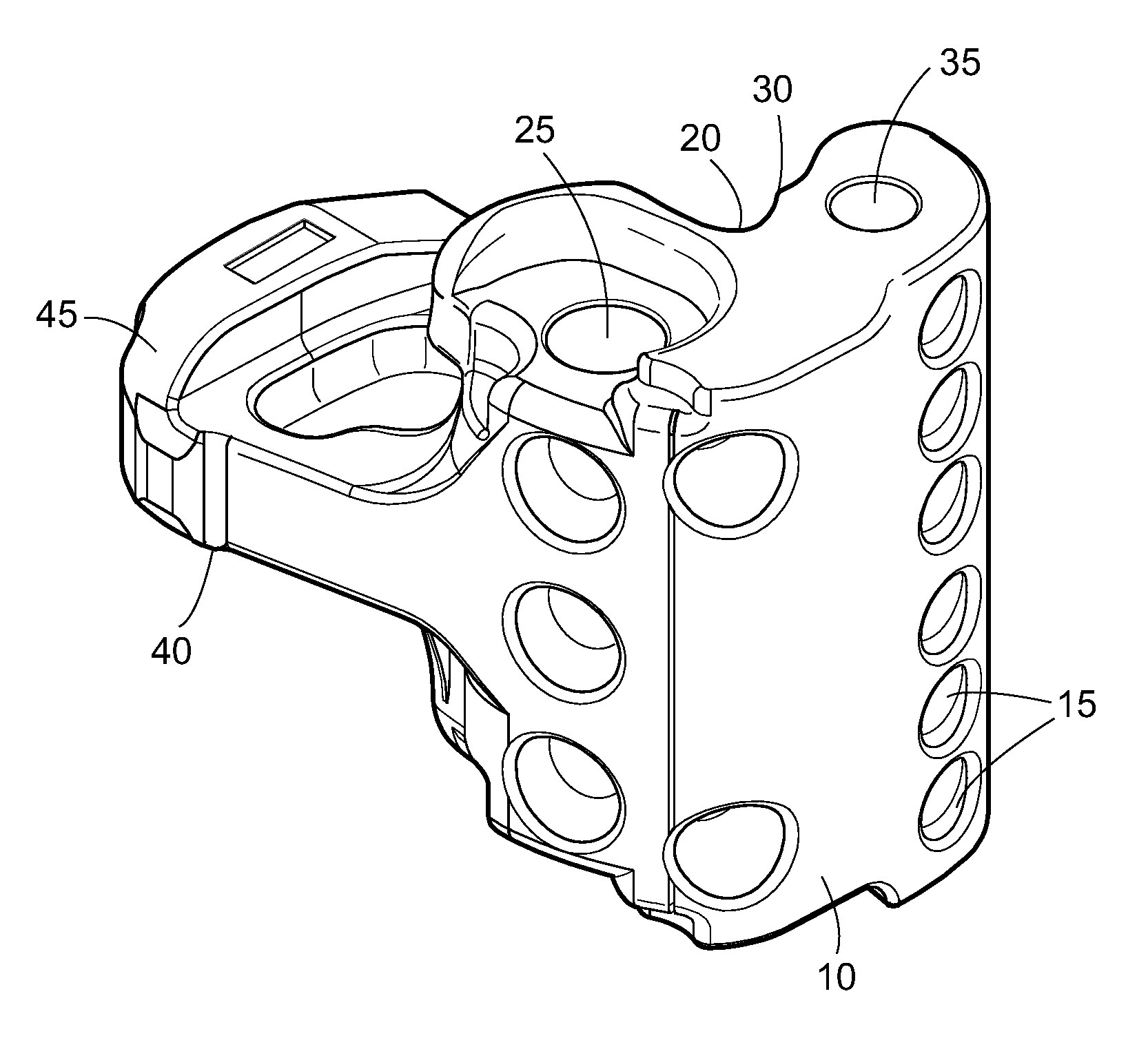
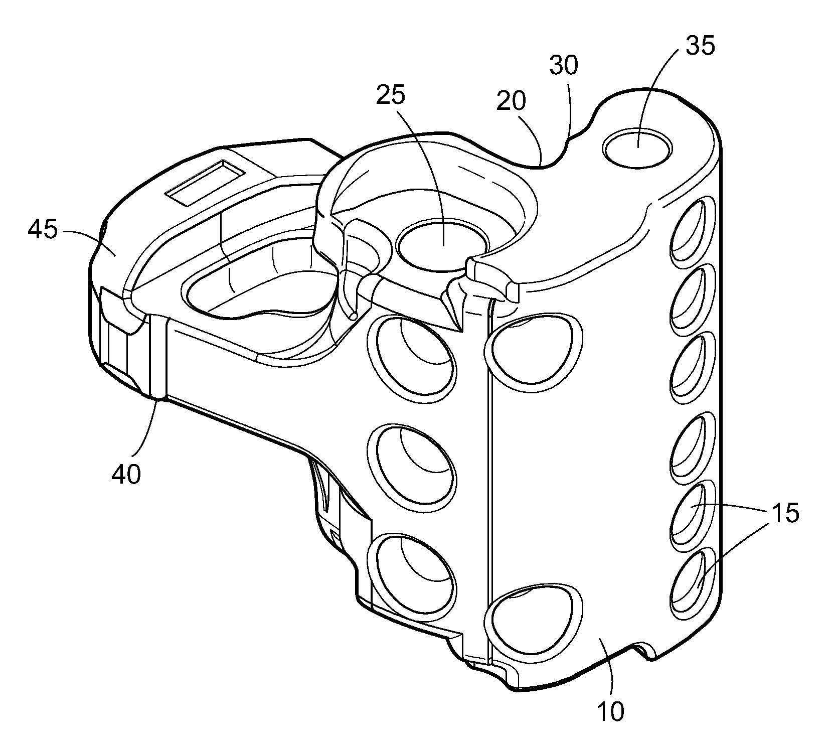
Knuckle for a railway car coupler

a technology for railway cars and couplers, applied in the field of railway car coupler systems, can solve the problems of prone to failure, premature failure, and inconsistent average fatigue life of knuckles, and achieve the effect of reducing porosity

Active Publication Date: 2012-10-30
STRATO AG
View PDF33 Cites 31 Cited by
  • Summary
  • Abstract
  • Description
  • Claims
  • Application Information

AI Technical Summary

Benefits of technology

"The present invention is a knuckle for a railway car coupler system that has a front portion with ribs and a pivot pin hole, and a tail portion with additional ribs. The knuckle is made by investment casting, which results in a smoother pulling face and reduced porosity. The knuckle has a weight of about 75 to 90 lbs and has a fatigue life of at least 600,000 cycles. The method also includes coating the knuckle with a temporary mold and destroying it after casting. The resulting knuckle has a surface roughness of less than 300 microinches."

Problems solved by technology

In a railway car coupler system, the knuckle element is the final point of contact between two railway cars, and the most prone to failure.
One evident problem with the core method is that it produces inconsistent results.
The core cannot be seen during the casting process, and it can move, causing the position of the internal voids and the internal wall thickness vary significantly in the finished products, with the result that the average fatigue life of knuckles is not consistent.
It has been discovered that relatively small point to point contact surfaces of the engaged portions of knuckles in a coupler system can cause premature failure due to stress risers being established within the knuckle.
Grinding and / or machining of such imperfect surface after heat treatment can add substantially increased costs and creates crack initiation sites on the surface, thereby adding stress to the coupler knuckle and potentially resulting in premature and unpredictable knuckle failure.
Without the draft angles, withdrawing the pattern from the mold cavity can result in the sidewalls partially collapsing or otherwise deforming.
However the draft angle yields a non-uniform contact surface area on the pulling face of the finished product.
Another inherent problem with the sand casing process is the porosity caused by moisture.
When the molten metal is poured into the mold, the moisture flashes to steam and may produce internal and surface porosity in the finished product.

Method used


Image

  • Knuckle for a railway car coupler
  • Knuckle for a railway car coupler

Examples


Embodiment Construction

[0013]As used herein, directions are relative to the normal orientation of a railway car. Thus, “horizontal” means generally parallel to the earth, and vertical is the perpendicular direction. The words “forward” and “front” refer to the direction away from the railway car, while “tail” and “rear” refer to the opposite direction. This means that the “front” ends of two coupler systems on adjacent railway cars face each other, in opposition directions. “E-type” and “F-type” are used to refer to types of coupler head generally, without reference to the details of a particular AAR standard. One of ordinary skill in the art will readily understand that a knuckle according to the invention may be for attachment to an “E-type” coupler head, even though the coupler may depart slightly from one or more AAR standards. Relative vertical motion between two F-type couplers is eliminated by interlocking features on the coupler head which are not present on the E-type coupler head. Although the k...


PUM


Abstract

A knuckle for a railway coupler system is made without internal voids or cores. Instead, external pockets are formed on the front face and tail portion surface to reduce weight. The knuckle is formed by investment casting, which permits a pulling face to be provided without a draft angle or parting line typical of a cast part. As a result of these innovations, the knuckle according to the invention has an improved fatigue life.

Description

BACKGROUND OF THE INVENTION[0001]1. Field of the Invention[0002]The invention is in the field of coupler systems for railway cars, and in particular, the invention is directed to a novel knuckle, adapted to engage with American Association of Railroads (“AAR”) type E and type F couplers.[0003]2. Description of Related Art[0004]In a railway car coupler system, the knuckle element is the final point of contact between two railway cars, and the most prone to failure. In some sense, the knuckle is designed to fail; because if any element in the coupler system is to fail, it should be the lightest and most accessible element, which is the knuckle. However, given the constraints of size, shape and weight, it is still desirable that a knuckle should be made as resistant to fatigue and failure as possible. Knuckle failure accounts for an estimated 11,000 train separations a year, or about 30 separations per day.[0005]Conventionally, a knuckle weighs approximately 78 to 88 pounds. However, a...

Claims


Application Information

Patent Timeline
Patent Type & Authority Patents(United States)
IPC IPC(8): B61G3/00
CPCB61G3/04B22C9/04
Inventor SMYTH, ANDREW
Owner STRATO AG
Learn More