Method for operating a hybrid drive system having a torque converter

a hybrid drive and torque converter technology, applied in the direction of machines/engines, engine starters, transportation and packaging, etc., can solve the problems of inability to activate the electric machine, slippage of the torque converter, and clearly perceptible jolt, and achieve the effect of constant torqu

Active Publication Date: 2012-10-30
ROBERT BOSCH GMBH
View PDF12 Cites 15 Cited by
  • Summary
  • Abstract
  • Description
  • Claims
  • Application Information

AI Technical Summary

Benefits of technology

[0006]It is provided according to the exemplary embodiments and / or exemplary methods of the present invention that, as a function of the rotational speed of the turbine wheel of the torque converter, a rotational speed is predefined for the electric machine such that no sudden torque change occurs at the hybrid drive output when the internal combustion engine is started. The rotational speed of the turbine wheel corresponds to the rotational speed at the output or at the output shaft of the torque converter and is therefore equal to the transmission input speed of a transmission connected downstream from the torque converter. If the rotational speed of the turbine wheel is known, a desired slip may be set in the hydraulic torque converter as a function of a transmitted torque by regulating the rotational speed of the electric machine. By setting the rotational speed of the electric machine as a function of the rotational speed of the turbine wheel, the rotational speed of the electric machine corresponding to the rotational speed of a pump wheel driving the turbine wheel, a sudden torque change may be prevented when starting the internal combustion engine, i.e., a constant torque may be ensured.
[0010]According to a refinement of the exemplary embodiments and / or exemplary methods of the present invention, the rotational speed of the electric machine is predefined as a function of a driver's input drive torque, so that the slip speed is continuously adapted to the driver's input drive torque, avoiding the feeling that the hybrid drive system is uncoupled from the accelerator pedal during the start operation of the internal combustion engine.
[0011]Another specific embodiment of the present invention is characterized in that the setpoint slip torque is limited as a function of an operating mode of the hybrid drive system. Therefore it is advantageous, for example, for an operating mode which makes a comfortable ride possible, if no sudden torque changes occur such as, for example, when the driver removes his foot from the accelerator pedal.
[0012]A zero crossing former may be used for limiting the setpoint slip speed. The zero crossing former limits the allowable rate of change in the slip speed as a function of the absolute value of the instantaneous slip speed. Smaller and smaller changes are allowed with decreasing slip speed. It is thus achieved that, in the event of a reversal of the sign of the torque, zero crossing takes place slowly and the drive train of the hybrid drive system is not disadvantageously excited.

Problems solved by technology

Since the actual slip torque of the disconnecting clutch cannot be accurately ascertained, it is not possible to activate the electric machine by simply using an appropriate additional torque.
The disadvantage here is that, if the motor vehicle accelerates or decelerates at the same time, the resulting slip of the torque converter changes.
In the event of a simultaneous gear shift, for example, this may reach the point where the direction of slip of the torque converter changes and thus the torque is reversed, which results in a clearly perceptible jolt.
However, since the route traveled, such as an upward or downward slope, is not known, the result is not reliably predictable.

Method used


Image

  • Method for operating a hybrid drive system having a torque converter
  • Method for operating a hybrid drive system having a torque converter

Examples


Embodiment Construction

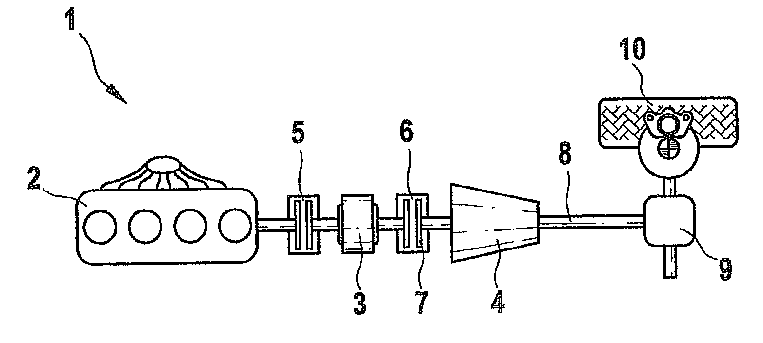
[0017]FIG. 1 schematically shows an exemplary embodiment of an advantageous hybrid drive system 1. Hybrid drive system 1 has an internal combustion engine 2, an electric machine 3, and an automatic transmission 4, which are connected in series, a disconnecting clutch 5 being situated between internal combustion engine 2 and electric machine 3, and a torque converter 6, of which only a lockup clutch 7 is depicted here, being situated between electric machine 3 and a hybrid drive output, which here represents the drive of transmission 4. At transmission 4, an output shaft 8 goes to a differential 9, from which the vehicle drive torque is transmitted, for example, to a wheel 10 depicted as an example. In the case of a purely electric drive, disconnecting clutch 5 is disengaged, so that only electric machine 3 is applying a drive torque to drive train 1. In order to start internal combustion engine 2 during the drive operation, disconnecting clutch 5 is engaged using a defined clutch to...


PUM


Abstract

A method for operating a hybrid drive system, in particular of a motor vehicle, having at least one electric machine and one internal combustion engine, a disconnecting clutch being provided between the electric machine and the internal combustion engine and a torque converter having a turbine wheel being provided between the electric machine and a hybrid drive output, the disconnecting clutch being engaged for starting the internal combustion engine. It is provided that, as a function of the rotational speed of the turbine wheel of the torque converter, a rotational speed is predefined for the electric machine such that no sudden torque change occurs at the hybrid drive output when the internal combustion engine is started.

Description

FIELD OF THE INVENTION[0001]The present invention relates to a method for operating a hybrid drive system, in particular of a motor vehicle, having at least one electric machine and one internal combustion engine, a disconnecting clutch being provided between the electric machine and the internal combustion engine and a torque converter having a turbine wheel being provided between the electric machine and a hybrid drive output, the disconnecting clutch being engaged for starting the internal combustion engine.BACKGROUND INFORMATION[0002]The above-described configuration of a hybrid drive system permits a purely electrical operation using the electric machine, the disconnecting clutch being disengaged and thus the internal combustion engine not being mechanically linked to the remaining drive train of the hybrid drive system. In this state, the internal combustion engine may be turned off in order to save fuel. Since it is not mechanically linked to the remaining drive train, it tra...

Claims


Application Information

Patent Timeline
Patent Type & Authority Patents(United States)
IPC IPC(8): B60W10/02B60W10/06B60W10/08
CPCB60K6/48B60L15/20B60W10/02B60W10/06B60W10/08B60W20/00B60L11/12B60L11/14B60K6/547B60L2240/421B60W2540/10B60W2710/081F16H2059/385Y02T10/6221Y02T10/6286Y02T10/642Y10T477/26Y10T477/79Y10T477/71Y02T10/72B60L50/16Y02T10/62Y02T10/64Y02T10/7072B60K2006/268F16H59/38B60W20/40Y02T10/70
Inventor SEEL, ANDREASSCHENK, RENEKAEFER, OLIVERJUENEMANN, THORSTEN
Owner ROBERT BOSCH GMBH
Why Eureka
Try Eureka