Marine lighting apparatus and method

a technology for marine vessels and lighting devices, applied in lighting and heating devices, semiconductor devices for light sources, instruments, etc., can solve the problems of heavy drain, inconvenient maintenance, and inability to meet the needs of marine vessels, so as to improve reliability, enhance operating life, and improve energy efficiency

Active Publication Date: 2012-11-06
EASTERN METAL SUPPLY
View PDF12 Cites 7 Cited by
  • Summary
  • Abstract
  • Description
  • Claims
  • Application Information

AI Technical Summary

Benefits of technology

[0008]The invention does not suffer from the disadvantages which have just been noted. One aspect of the invention relates to a marine lighting device which is mountable in-line with a member of tubular marine vessel structure such as a T-top, fishing tower, hand rail or the like. Structural integrity of the member can be maintained, and general or task illumination provided in an aesthetically pleasing manner owing in part to the ability of the invention to provide visual continuity of the profile of the lighting device with the tubular member resulting from their mutual longitudinal axial alignment as well as from maintaining substantially the same structural geometry of the marine vessel structure as was present prior to installation of the lighting device. Owing to use of light emitting diodes as a light source, high energy efficiency as well as improved reliability, enhanced operating life and immunity to shock and vibration as compared to conventional devices is provided.
[0009]A marine lighting device according to a preferred embodiment incorporates a linear array of multiple individual LEDs of any desired color or combination of colors. If desired, these can be wired such that the number, color, (or combination of colors) and location of various ones of the individual LEDs, or subgroups of the LEDs in the array can be independently controlled. For example, the device may incorporate one or more groups of white LEDs and one or more groups of LEDs. The white LEDs can be wired for switching off and on as desired to provide general illumination. However, for uses such as night fishing or in pilot areas when navigating at night, the red LEDs would be used in order to allow improved night vision.

Problems solved by technology

However, many suffer from one or more significant drawbacks.
Incandescent lamp devices are generally energy inefficient and tend to place a heavy drain on marine batteries and demand on the capacity of the electrical power generators of marine vessels.
Their illumination output per watt of electrical input power tends to be low.
Incandescent lamps also have a relatively low operating life which, due to the heavy vibration associated with marine vessel applications is shortened even further.
Gaskets of this type are subject to rapid degradation due to sunlight, solvents, and fuel, which are very often present in marine vessel environments where such lights are needed.
They are also susceptible to damage and improper re-installation when the incandescent lamps are replaced.
When the sealing ability of these gaskets is compromised, the device is readily infiltrated by seawater, or fresh water causing short circuits, corrosion and other type of failures.
Accordingly, they too are subject to damage and failure due to water infiltration when their seals are compromised.
Gas discharge lamps are also vulnerable to vibration damage and usually require electrical ballasts which make them expensive, bulky and often difficult to install.
Unless installed during the process of building the marine vessel in which they are used, many marine lighting devices are difficult to install.
As such, they do not provide an aesthetically pleasing installed appearance and are more prone to damage or being knocked loose.
More importantly, they occupy free space which is often limited in marine vessels and present obstructions which can be hazardous or interfere with safe and easy operation and use of this vessel.

Method used


Image

  • Marine lighting apparatus and method
  • Marine lighting apparatus and method
  • Marine lighting apparatus and method

Examples


Embodiment Construction

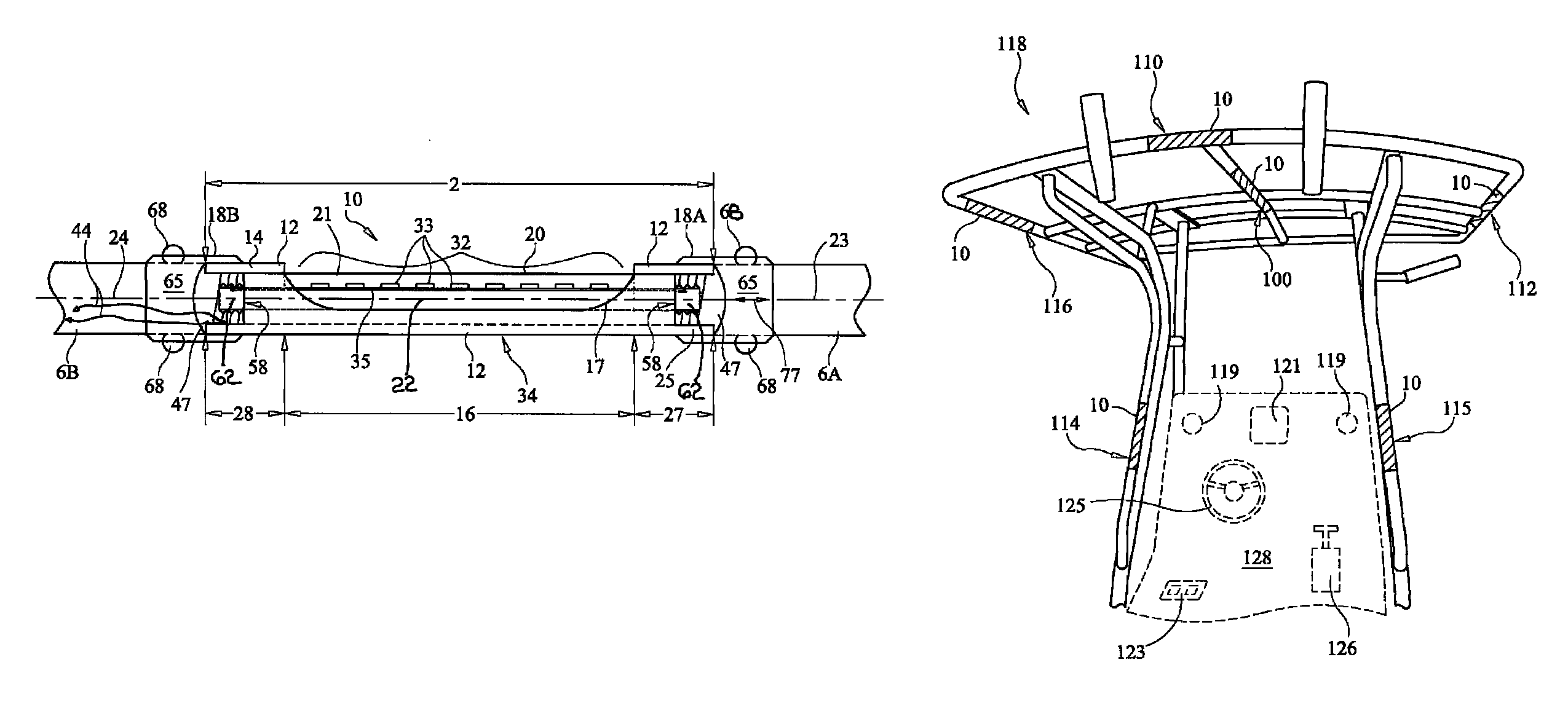
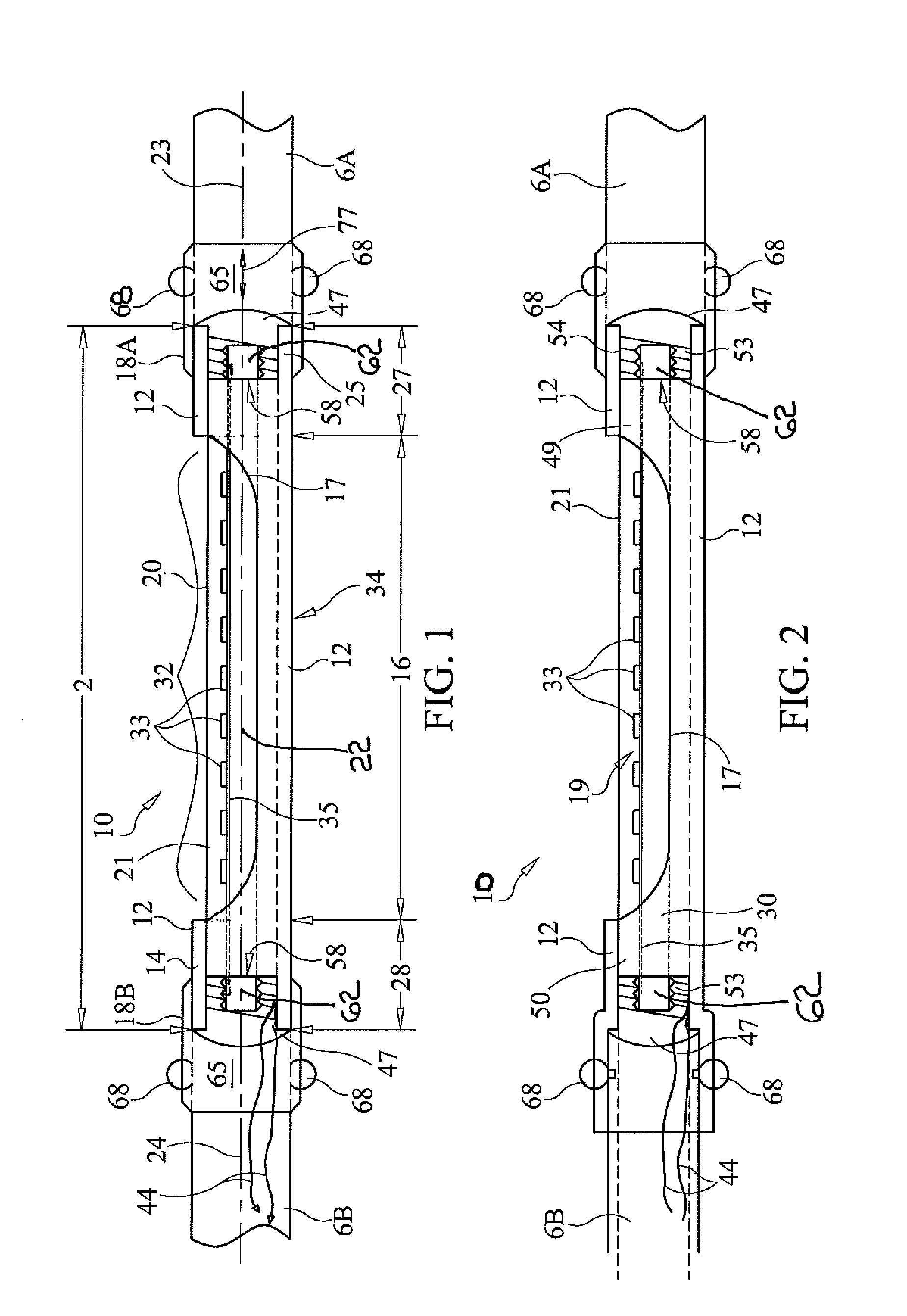
[0021]A first preferred embodiment of a marine lighting device 10 according to the invention is suitable for mounting longitudinally in-line with a tubular member of a marine vessel structure and will now be described with reference to FIG. 1. Device 10 is mountable in a gap 2, present between opposed free ends 3, 4 of tubular member(s) 6A, 6B of a marine vessel structure. Device 10 has a tubular housing 12 whose outer wall 14 includes a partially open, or partially cutaway, central portion 16 which includes an edge 17 which defines the periphery of an opening 19 through which illumination may be emitted. Housing 12 has opposed ends 25, 26 and is preferably of a material such as brass, stainless steel or anodized aluminum having a wall thickness sufficient to provide sufficient mechanical strength for the application at hand. Housing 12 may be for example of polished anodized aluminum. Preferably, the strength of housing 12 is at least comparable to, and most preferably is greater t...


PUM


Abstract

A marine lighting device mounts in-line with a tubular member of a marine vessel structure such as a T-top, tower or hand rail. An LED light bar having an array of LEDs supportably mounted to a circuit board is sealably enclosed in a tubular lens which, in turn is disposed within a tubular housing, a central portion of which is provided with an opening through which illumination from the LEDs is emitted after passing through the lens. A sleeve coupling is used to mount at least one end of the housing to a free end of the tubular member. In lieu of using a sleeve coupling at both ends one end of the housing may be flared to receive one of the free ends of the tubular member. A lighted T-top incorporating at least one such marine lighting device and a lighted marine handrail are also disclosed.

Description

CROSS-REFERENCE TO RELATED APPLICATIONS[0001]This application claims priority under 35 U.S.C. §119(e) to U.S. Provisional Application Ser. No. 61 / 109,844 filed Oct. 30, 2008 for all commonly disclosed subject matter. U.S. Provisional Application Ser. No. 61 / 109,844 is expressly incorporated herein by reference in its entirety to form a part of the present disclosure.FIELD OF THE INVENTION[0002]The invention relates to the field of artificial lighting for marine vessels. More particularly the invention relates to a marine lighting device, a method of mounting same in a T-top, control tower or like marine vessel structure and a lighted handrail.BACKGROUND OF THE INVENTION[0003]Various types of artificial lighting devices for illuminating interior and / or exterior portions of marine vessels are known in the prior art. However, many suffer from one or more significant drawbacks. Incandescent lamp devices are generally energy inefficient and tend to place a heavy drain on marine batteries...

Claims


Application Information

Patent Timeline
Patent Type & Authority Patents(United States)
IPC IPC(8): B60Q1/00
CPCB63B45/04F21S4/008F21Y2101/02F21Y2103/003F21S4/28F21Y2103/10F21Y2115/10
Inventor WILCOX, SCOTT A.
Owner EASTERN METAL SUPPLY
Why Eureka
Try Eureka