Forward-looking synthetic aperture radar processing

Inactive Publication Date: 2012-11-06
MARK RESOURCES
View PDF1 Cites 7 Cited by
  • Summary
  • Abstract
  • Description
  • Claims
  • Application Information

AI Technical Summary

Benefits of technology

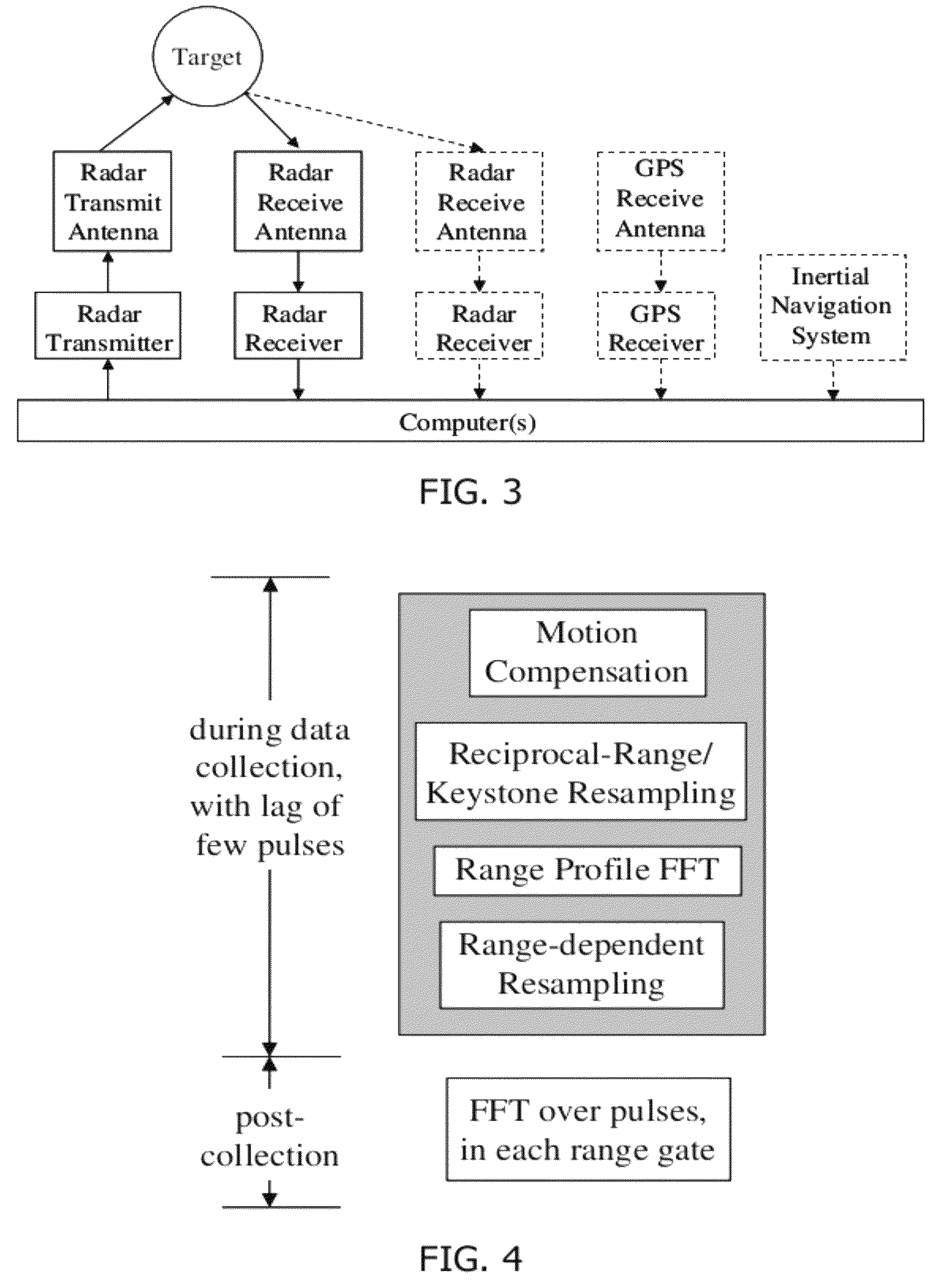
[0023]During the longer integration interval enabled by reciprocal-range resampling, scatterers may drift through range resolution cells, with the drift increasing with the distance of the scatterer from the radar trajectory. The range drift of a scatterer, even at constant range-rate ∂Rc / ∂θ with respect to the new reciprocal-range coordinate, will also broaden the scatterer's image response in crossrange. The linear (in reciprocal-range) component of the drift and the consequent response broadening in range and crossrange can be eliminated by the application of keystone processing. (See Perry, R. P., et al., “SAR Imaging of Moving Targets”, IEEE Trans. AES, January 1999, pp. 188-200.) Keystone processing may be implemented by defining a new coordinate θ′=(f / fc)θ at each sampled frequency f of the radar bandwidth, where fc is the radar carrier frequency, and then resampling the data to obtain samples spaced evenly in the new coordinate.
[0031]In a monopulse or interferometric radar system, the processing described herein may be applied to each receiver channel and they may be combined via conventional processing (e.g., amplitude-amplitude monopulse, phase-phase monopulse, sum-and-difference monopulse, combination monopulse; additive interferometry, multiplicative interferometry) to measure the physical position of each image response. The better resolution and compression provided by the invention will result in improved accuracy for these systems. The improved accuracy of the physical position determined by monopulse or interferometry, as well as that of the two-dimensional position (zk,ρk) calculated from the image response location, increases the efficacy of using inconsistency in the two measurements to recognize responses from multipath reflection or rotating objects.Moving Targets
[0033]When the signal-to-clutter ratio (SCR) of a moving target is high, an alternative embodiment is preferred. Under these conditions, the radar can directly measure the range to the target and the relative speed of the radar and target. The measured speed is used in (13) through (16). This yields better-focused responses and more accurate measurements of scatterer positions. The alternative embodiment provides the same degree of focus for a target moving at constant velocity as the exemplary embodiment does for a stationary target (the two embodiments are equivalent in the target rest frames). The better-focused responses of this embodiment enable more accurate measurements of physical positions via monopulse or interferometric processing.

Problems solved by technology

Most widely used SAR image formation algorithms (Polar Format Algorithm, Range Doppler Algorithm, Chirp Scaling Algorithm, Back Projection Algorithm) approximate the range variation in ways that work to varying degrees for side-looking SAR, but work poorly for forward-looking SAR.
That is, these algorithms do not provide a well-focused image of the region toward which the platform is moving.
Moreover, the algorithm requires a time-consuming processing step (Stolt interpolation) that cannot be executed until all the data used to form the image have been collected, which makes the algorithm poorly suited for use in real time by fast-moving platforms; data collection must cease at such a long range from an object to be imaged that only crude crossrange resolution can be obtained.
Approximate versions of the Omega-K Algorithm replace Stolt interpolation with a faster step, but this replacement works poorly for forward-looking SAR (see Cumming, I. G. and F. H. Wong, Digital Processing of Synthetic Aperture Radar Data: Algorithms and Implementation, Artech House, 2005).

Method used


Image

  • Forward-looking synthetic aperture radar processing
  • Forward-looking synthetic aperture radar processing
  • Forward-looking synthetic aperture radar processing

Examples


##ic embodiment

Bistatic Embodiment

[0035]The exemplary embodiment above is monostatic, with the radar transmitter and receiver on the same platform. An alternative bistatic embodiment, with the transmitter and receiver on separate platforms, employs the same processing wherein range and relative speed are those between the radar receiver and the target, except for the measurement of scatterer position. For the bistatic embodiment, Ckand Rk in (15) and (16) denote twice the image crossrange and range positions (in resolution cells) of response k, respectively.

Illustration of Invention

[0036]To illustrate the invention, specific parameters of the exemplary embodiment will be chosen and the radar returns and their processing will be simulated. The illustration simulates the returns from five point scatterers at the corners and center of a horizontal square 10 m on a side, plus a sixth point scatterer above the center and separated from it by the same distance as the corners. The radar travels 0.15 seco...


PUM


Abstract

Processing is described for forming a synthetic aperture radar image of the region toward which a platform moves, and for extracting from this image the physical positions of scatterers in the region, including moving scatterers. The processing entails one-dimensional resampling of the received radar data that can be performed as the data are being collected, facilitating real-time operation. Various embodiments are disclosed.

Description

STATEMENT OF GOVERNMENT INTEREST[0001]The U.S. Government has certain rights in this invention pursuant to Contract No. FA8651-07-M-0184 awarded by the Air Force.BACKGROUND OF THE INVENTION[0002]1. Field of the Invention[0003]The present invention relates to the fields of synthetic aperture radar, fuze radar, collision avoidance radar, and precision approach and landing radar.[0004]2. Prior Art[0005]Synthetic Aperture Radar (SAR) uses a series of radar pulses transmitted and received over time from a moving platform to create a range-crossrange image. The bandwidth of the radar provides range resolution and the angular rotation of the radar line of sight with respect to the scene to be imaged provides crossrange resolution. The formation of a perfectly focused image requires accounting for the time-varying range to each point in the scene, which variation differs from point to point. Most widely used SAR image formation algorithms (Polar Format Algorithm, Range Doppler Algorithm, Ch...

Claims


Application Information

Patent Timeline
IPC IPC(8): G01S13/00
CPCG01S13/003G01S13/9035G01S2013/907G01S13/904G01S13/9043G01S13/9092
InventorHERSHKOWITZ, STEPHEN J.
OwnerMARK RESOURCES