Liquid container and liquid container package

a technology which is applied in the field of liquid container and package, can solve the problems of printing subject's insufficient density, insufficient dispersibility of pigment components of coloring materials in ink, and various handling problems of pigment ink, and achieve the effect of small variation in the concentration distribution of coloring materials

Active Publication Date: 2012-11-20
CANON KK
View PDF51 Cites 22 Cited by
  • Summary
  • Abstract
  • Description
  • Claims
  • Application Information

AI Technical Summary

Benefits of technology

[0019]In consideration of the abovementioned points, an object of the present invention is to provide a liquid container which allows a user to unconsciously and naturally perform a stirring operation of a coloring material component inside a tank by performing a series of procedures for mounting the tank in the apparatus; and which thus has a small variation in concentration distribution of the coloring material.
[0020]In addition, another object of the present invention is to provide a liquid container package that makes it possible to stir a coloring material component inside an ink tank, and thereby to obtain a state where the coloring material is uniformly distributed.
[0023]According to the present invention, air existing in the liquid container (an ink tank) moves along with an operation of turning over a side face having an ink supply port of the tank, and another side face opposite to the foregoing side face. In the course of this movement of the air, the air is separated by a structure inside the tank. As a result, stirring of liquid (mainly pigment ink) is promoted by the movements of the separated air inside the tank. Thereby, the present invention has an effect that an improved state of the distribution of component (mainly a coloring material) inside the liquid container (the ink tank) can be obtained only by requiring a minimum of stirring operation.
[0024]The liquid container package according to the present invention has an effect that stirring of a coloring material inside the liquid container can be performed in the course of carrying out a series of procedures which start from a state where the container is wrapped in the package, and end with a completion of mounting the container in the printing apparatus. To be more precise, the liquid container package has the effect that a stirring operation is naturally performed in the course of carrying out a procedure of: breaking the pack member so as to take out the liquid container from the package; and then mounting the liquid container thus taken out in the printing apparatus.

Problems solved by technology

However, in comparison with the dye ink, the pigment ink has various problems in terms of handling.
For example, dispersibility of pigment component of a coloring material in the ink is one of the problems.
Then, a printed subject may possibly have an insufficient density that cannot be expressed properly even if the printed subject is printed in accordance with the same image data as that used at the start of the printing.
Particularly, the large diameter or the large specific gravity of pigment particle results in a remarkably large settling tendency.
In this case, it leads to uneven distribution of the dye component itself in the ink tank, and a concentration gradient sometimes occurs in the dye ink although the gradient is not as severe as that in the case of the pigment ink.
As has been described above, the variation in concentration of a coloring material of ejected ink causes not only a problem of generating a density variation between output images in an earlier stage and a later stage in using an ink tank; but also the collapse of a color balance in a color inkjet printing system which expresses a desired hue under a predetermined color balance by using a plurality of color inks.
Accordingly, this produces a problem that the unevenness in an image causes the image deterioration to be recognized.
However, such an active stirring operation cannot be performed during the unused period.
As a result, settling of a coloring material or pigment component progresses, and the variation in concentration distribution in a vertical direction of the tank may become extremely large in some cases.
In a state where such large variation in concentration distribution have been generated, that is, a state where the coloring material is concentrated near an ink supply port, it becomes more difficult to reduce the variation in concentration distribution.
A stirring effect cannot be sufficiently obtained in some cases at an early stage after the tank is mounted, even if the ink stirring operation inside the tank is performed by pressurizing and decompressing the ink supply path, such as the tube, connected to the tank.
This situation brings about a conflicting problem therebetween.

Method used


Image

  • Liquid container and liquid container package
  • Liquid container and liquid container package
  • Liquid container and liquid container package

Examples


first embodiment

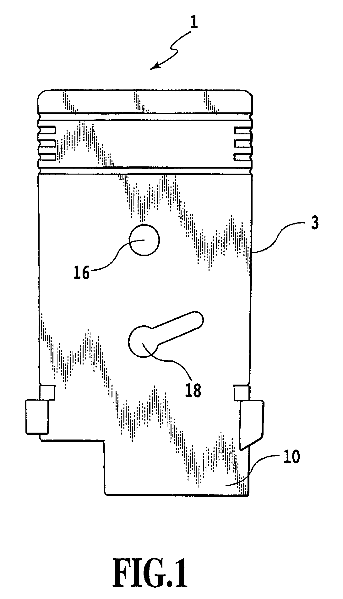
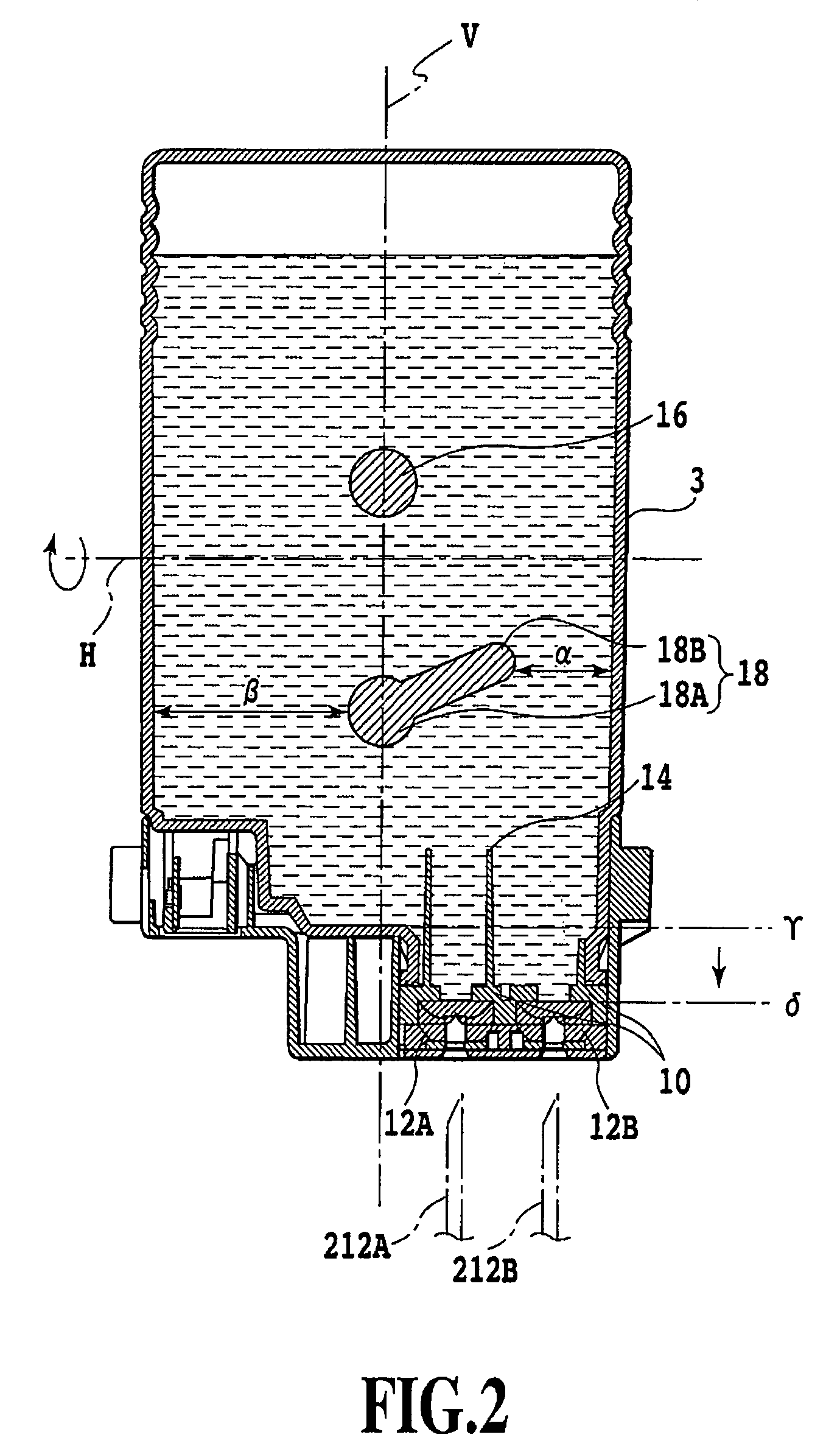
[0046]FIG. 1 is a side view showing an ink tank according to a first embodiment of the present invention.

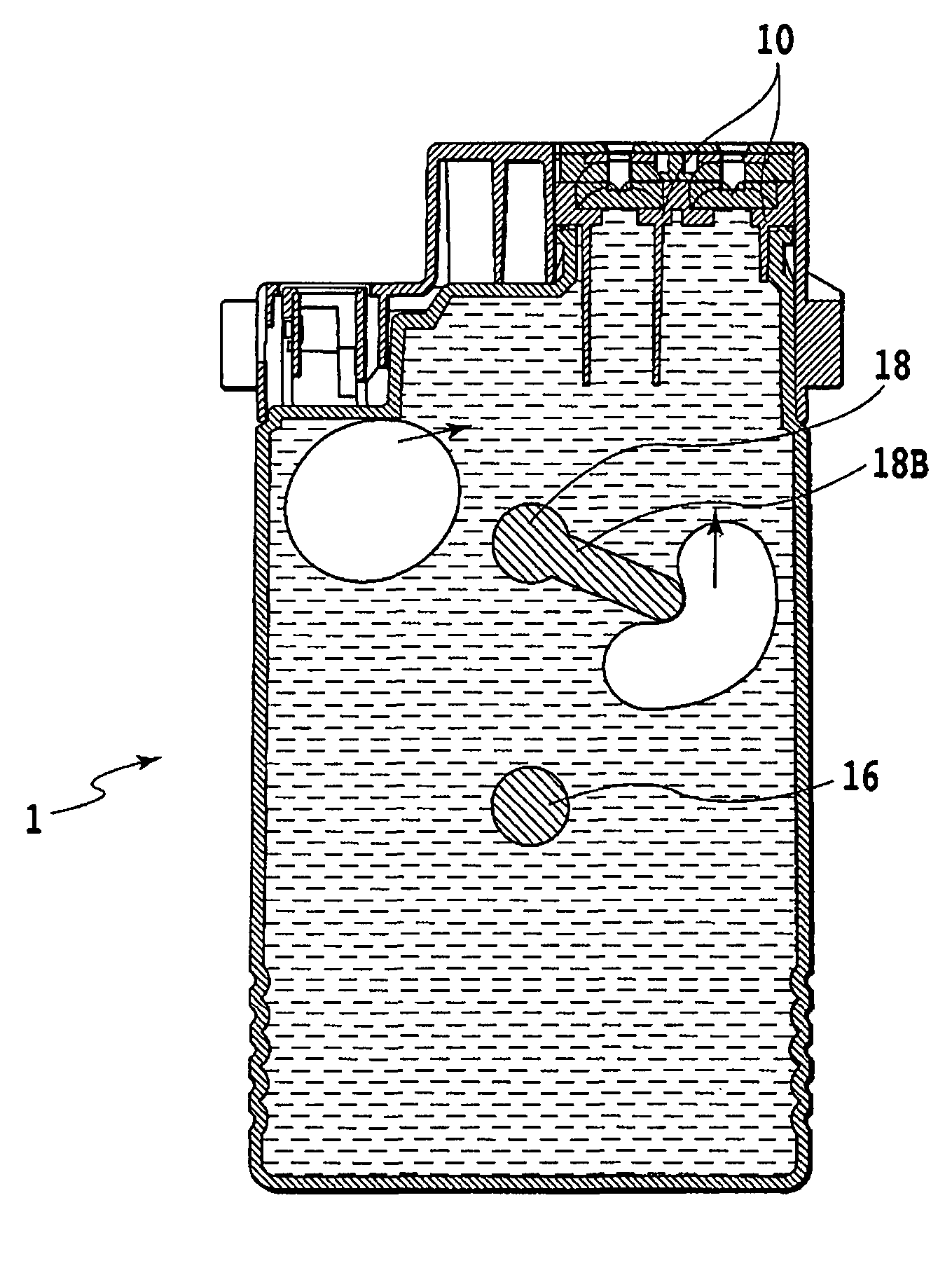
[0047]An ink tank 1 contains pigment ink of a color (for example, black, cyan, magenta, yellow or the like) aligned with a configuration of a printing apparatus part. The ink tank 1 is made of resin, such as, for example, PP or PE, and formed by using injection blow molding or the like. Each of components of the ink tank 1 is constructed by use of a technique such as ultrasonic welding, thermal welding, bonding or fitting. The ink tank 1 includes a tank casing 3 directly functioning as an ink containing portion. The tank casing 3 has a shape of a substantially rectangular solid. One of side faces of the tank casing 3 (hereinafter, defined as a front face) shown in FIG. 1 and another side face thereof opposite to the front face (hereinafter, defined as a back face) are faces forming the maximum areas of all faces of the rectangular solid shape.

[0048]The ink tank 1 is detachable fr...

second embodiment

[0066]The ink tank is not limited to the above described embodiment, and may have various configurations.

[0067]FIGS. 13 and 14 are a side view and a cross-sectional view, respectively, which show an ink tank according to a second embodiment of the present invention. The same reference numerals are given to locations corresponding to the members configured and arranged in the same manners as those in the aforementioned first embodiment.

[0068]In the case of an ink tank 100 in the present embodiment as well, a tank casing directly functions as an ink chamber, and contains a predetermined amount of air. Although the ink tank 100 of the present embodiment also has a shape of a substantially rectangular solid, an end portion opposite to an end potion having an ink supply portion 10 is formed into a torus structure, and can be grasped by a user when the user handles the ink tank. The torus structure is configured to be hollow, and allows fluid to exist inside the torus. This torus structur...


PUM


Abstract

When a package in which a tank 1 is wrapped is opened, caused is an action of reversing vertical positions of an end face of the tank 1 having an ink supply portion 10, and an end face opposite to the foregoing end face. Along with this action, air existing inside the tank 1 ascends, and then is separated by air separating portions. Thus, a coloring material component inside the tank is stirred.

Description

BACKGROUND OF THE INVENTION[0001]1. Field of the Invention[0002]The present invention relates to a liquid container and a package thereof. More specifically, the present invention relates to: a liquid container suitable for storing liquid such as ink used in inkjet printing; and a package thereof. In addition to a general printing apparatus, the liquid container of the present invention is also applicable to apparatuses such as: a copying machine; a facsimile having a communication system; and a word processor having a printing unit. Furthermore, the liquid container is also applicable to a liquid supply source of an industrial printing apparatus combined in a complex manner with various kinds of processing apparatuses.[0003]2. Description of the Related Art[0004]In an inkjet printing apparatus, a printing head and a liquid container (hereinafter, also referred to as an ink tank) are used in general. The ink tank is connected to the printing head, and thereby supplies liquid such as...

Claims


Application Information

Patent Timeline
Patent Type & Authority Patents(United States)
IPC IPC(8): B41J2/19
CPCB41J2/17513
Inventor HATASA, NOBUYUKIKOTAKI, YASUOINOUE, RYOJI
Owner CANON KK
Why Eureka
Try Eureka