Self-adjusting wedge bumper

a wedge bumper and self-adjusting technology, applied in the direction of mechanical equipment, weapons, transportation and packaging, etc., can solve the problems of extreme environmental changes missile and container rattling and shaking, etc., to minimize the rattle space, minimize the friction force, and reduce the effect of assembly and disassembly

Inactive Publication Date: 2012-11-27
SAN DIEGO COMPOSITES
View PDF19 Cites 45 Cited by
  • Summary
  • Abstract
  • Description
  • Claims
  • Application Information

AI Technical Summary

Benefits of technology

[0018]In an alternate embodiment, opposed dowel pins mounted to the upper surface of the lower wedge and externally to the upper wedge prevent the upper wedge from being dislocated from the lower wedge.
[0019]The wedge bumpers may be adapted to any application where it is desirable to minimize rattle space between an object and its container. Such applications include, without limitation, land or air transport of fragile or breakable objects such as mirrors, glass objects, telescopes, satellites, electronic equipment, and any equipment or object being launched into space either independently (i.e., through missile/rocket launch) or as part of a larger object being launched (e.g., equipment on a shuttle). The bumpers also may be adapted to situations in which it is desirable

Problems solved by technology

For example, the missile will experience rattling and shaking during transport from its production point to a silo.
The missile and its container also experience environmental changes over time while the missile is in storage.
In addition, the missile and container will experience extreme environmental changes (primarily extreme heat) upon missile egress.
For example, over the life of the missile, a missile composite motor case may absorb moisture resulting in swelling of the motor case skin.
However, the shims are not capable of adjustment to accommodate changes in the radius of the container, and they are limited in their ability to counteract the movement of the container

Method used


Image

  • Self-adjusting wedge bumper
  • Self-adjusting wedge bumper
  • Self-adjusting wedge bumper

Examples


Embodiment Construction

[0031]The following detailed description illustrates the invention by way of example, not by way of limitation of the scope, equivalents or principles of the invention. The nature, objectives and advantages of the invention will become more apparent to those skilled in the art after considering the following detailed description in connection with the accompanying drawings.

Self-Adjusting Wedge Bumper

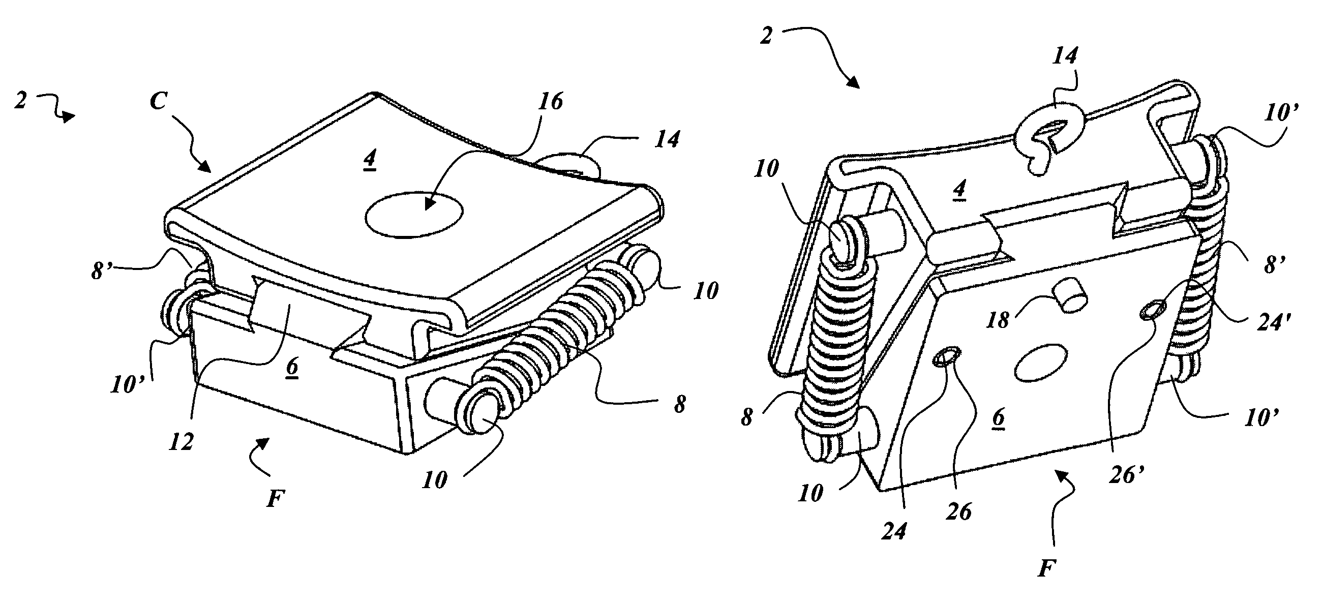
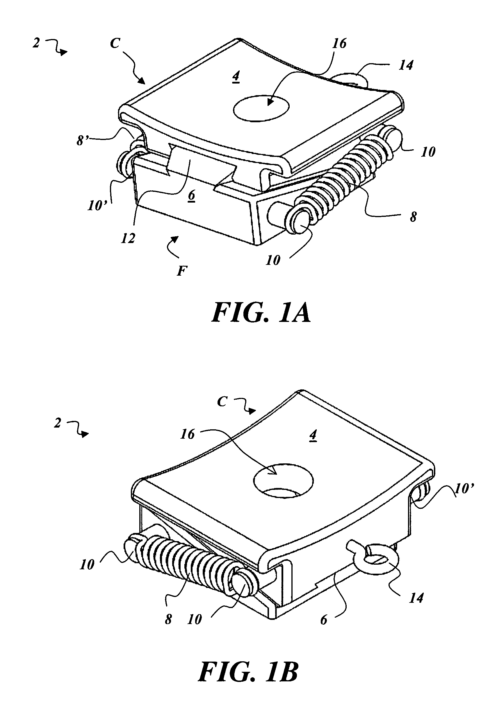
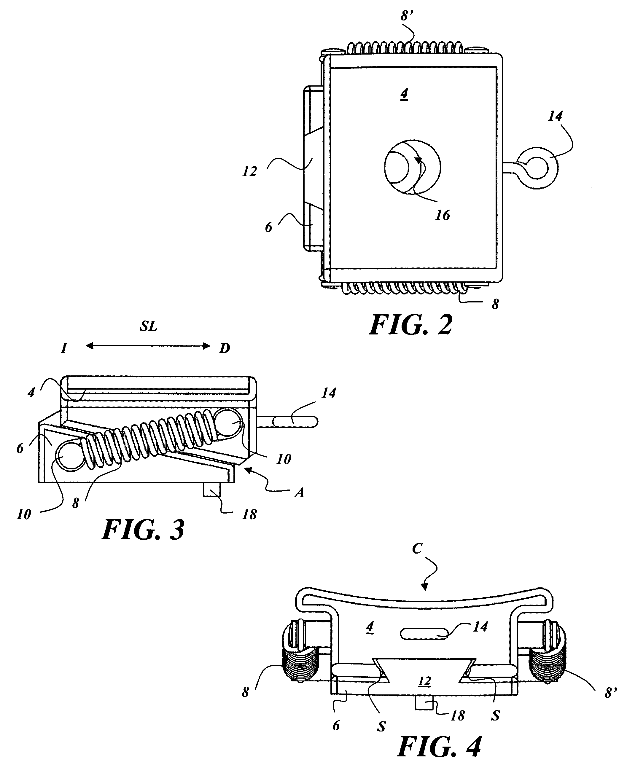
[0032]FIGS. 1A and 1B show perspective views of the wedge bumper 2 comprising a generally rectangular-shaped tapered upper wedge 4 overlapping a generally rectangular-shaped tapered lower wedge 6. The lower wedge 6 has a primary, dovetail-shaped guide rail 12 coupled thereto. Opposing springs 8, 8′ are mounted to opposing machine hook pins 10, 10′ coupled to the sides of the upper and lower wedges 4, 6. As shown in reference to FIGS. 5 and 6, the preferred embodiment comprises secondary internal guide pin rails 24, 24′ extending from the top face of the lower wedge 6 and corresponding gu...


PUM


Abstract

A self-adjusting bumper comprising slidably adjustable upper and lower tapered nylon wedges for eliminating rattle space between objects and their containers. A tapered lower wedge comprises a dovetail guide rail and opposing guide pin rails; a tapered upper wedge comprises a corresponding dovetail guide path and opposing slots shaped for insertion and slidable adjustment of the guide pin rails. Opposing helical extension springs secured to the sides of the upper and lower wedges minimize friction forces between the wedges as they slidably move relative to one another. External surfaces of the wedges may be contoured to accommodate the shape of the object and/or its container.

Description

CROSS REFERENCE TO RELATED APPLICATION[0001]This application claims priority under 35 USC 119(e) of Provisional Patent Application Ser. No. 60 / 904,248 filed Mar. 1, 2007, entitled “Self-Adjusting Wedge Bumper System,” which is hereby incorporated by reference in its entirety.GOVERNMENT RIGHTS CLAUSE[0002]The U.S. Government has a paid-up license in this invention and the right in limited circumstances to require the patent owner to license others on reasonable terms as provided for by the terms of SPARTA Subcontract No. 05-1015 funded by the Raytheon Company and the Army NLOS-LS Project.FIELD OF THE INVENTION[0003]This invention relates generally to shock and vibration isolation systems to minimize rattle space, and more particularly to a self-adjusting wedge bumper apparatus and system for transport, storage, and / or operation / removal of objects within containers, including without limitation, missiles transported, stored and operated from the same container.BACKGROUND OF THE INVENT...

Claims


Application Information

Patent Timeline
IPC IPC(8): B65D81/02
CPCF42B39/22F41F3/042F41F3/052F16F15/067
Inventor KOLOZS, ROBERT T.MOORE, JOSH S.
Owner SAN DIEGO COMPOSITES
Why Eureka
Try Eureka