
Optical sheet manufacturing method

a manufacturing method and technology of optical sheets, applied in the field of optical sheets, can solve the problems of requiring extra steps, requiring a correspondingly longer production line and larger installation space, and stacking light condensing sheets and light diffusing sheets to meet this need, and achieve the effect of reducing the number of manufacturing steps and thinning the film

Active Publication Date: 2012-11-27
FUJIFILM CORP
View PDF12 Cites 0 Cited by
  • Summary
  • Abstract
  • Description
  • Claims
  • Application Information

AI Technical Summary

Benefits of technology

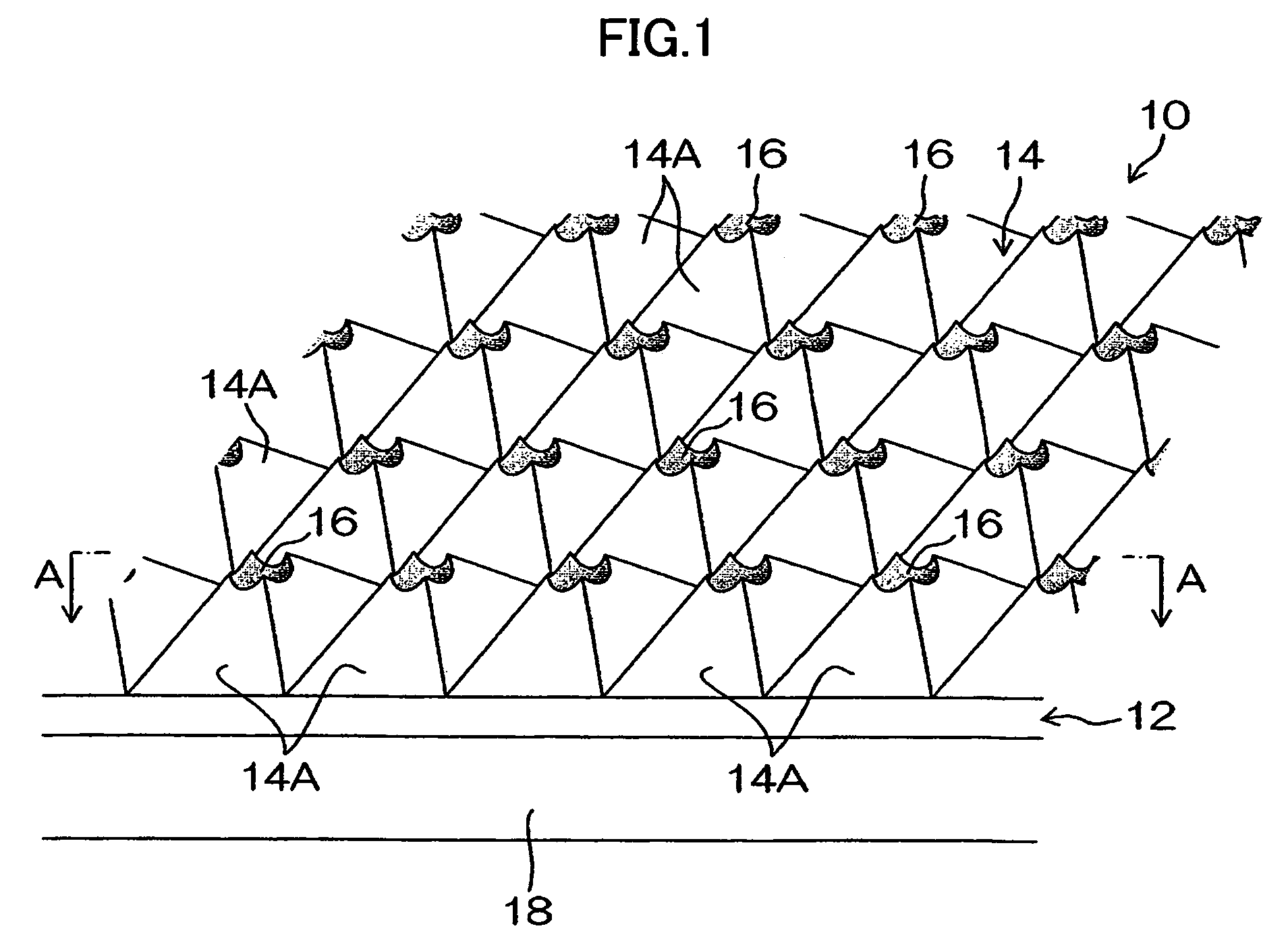
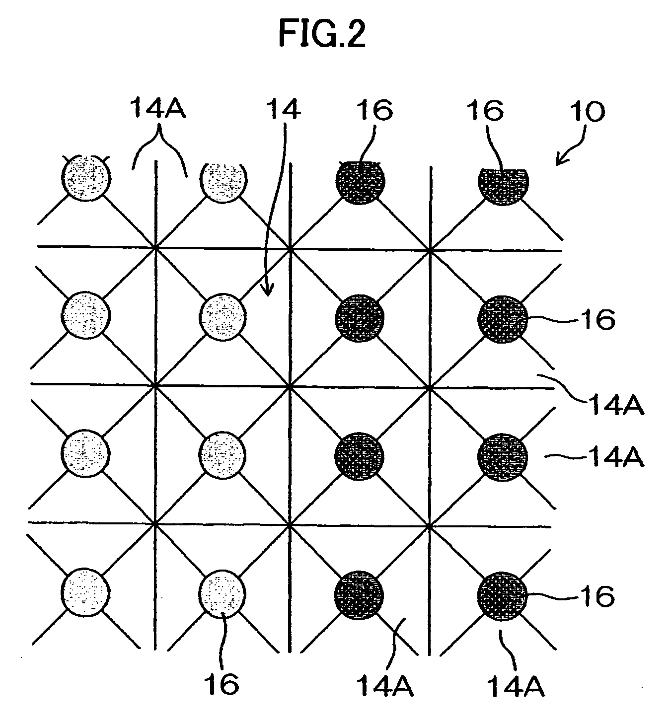
The present invention provides an optical sheet that combines both a light condensing function and a light diffusing function in a single sheet, reducing the number of manufacturing steps and the thickness of the film. The optical sheet has a plurality of micro-dimples formed in the convex-concave face of a resin sheet, which can exert both light condensing and light diffusing functions. The micro-dimples are smaller than the convexes and concaves of the convex-concave pattern, and can be positioned at the vertexes of the concave quadrangular pyramids or in the edge lines of the concave quadrangular pyramids. The optical sheet can be manufactured using a method described in another patent.

Problems solved by technology

However, any conventional optical film which has both the light condensing function and the light diffusing function is formed by stacking a light diffusing sheet and a light condensing sheet one over the other, and therefore requires a stacking step of stacking the manufactured light condensing sheet and light diffusing sheet and the sticking step of making the stacked sheets firmly adhere to each other besides individually manufacturing the light condensing sheet and the light diffusing sheet, resulting in a problem of requiring extra steps.
The extra steps mean the need for a correspondingly longer production line and larger installation space.
Furthermore, the recent trend of favoring thinner liquid crystal display devices necessitates minimization of the optical film thickness, but stacking a light condensing sheet and a light diffusing sheet does not meet this necessity.

Method used


Image

  • Optical sheet manufacturing method
  • Optical sheet manufacturing method
  • Optical sheet manufacturing method

Examples


implementation examples

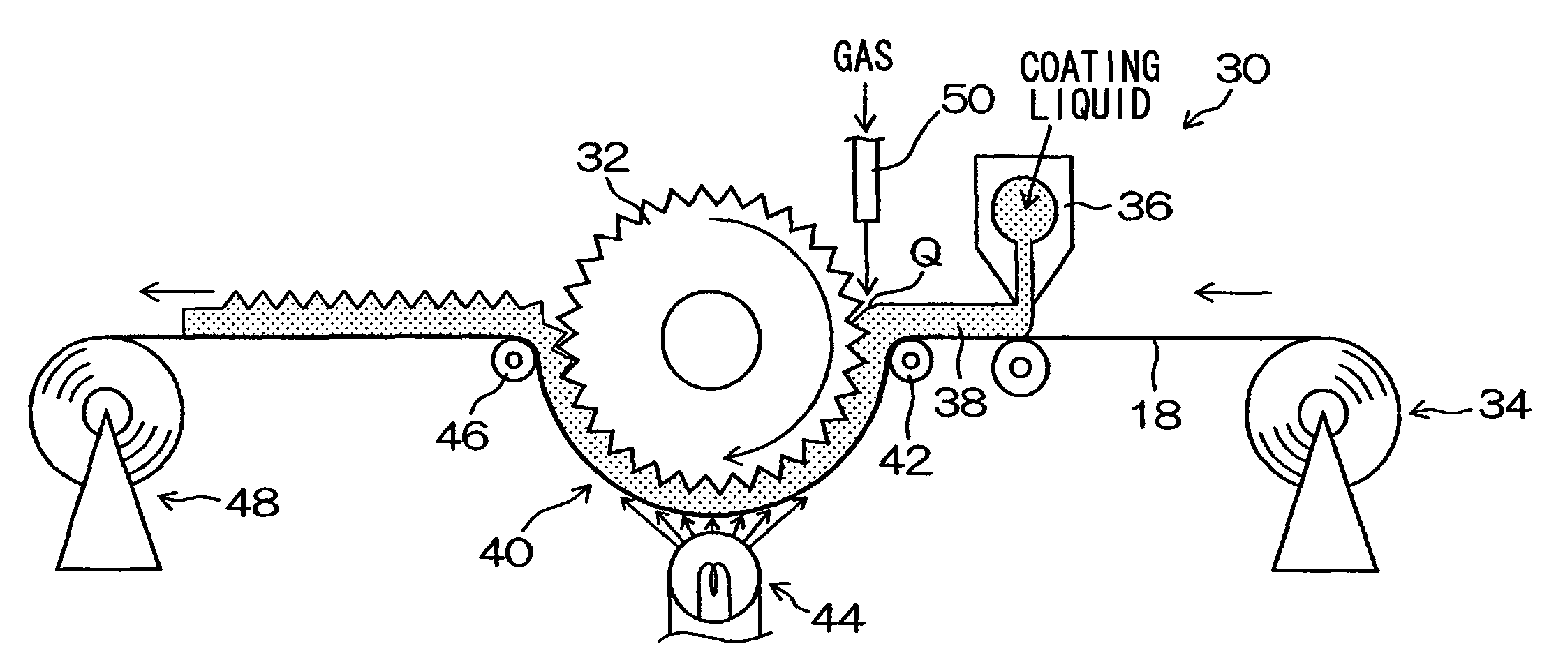
[0077]Next, implementation examples in which the optical sheet 10 was manufactured by using the manufacturing apparatus 30 shown in FIG. 12 will be described, but the implementation of the invention is not limited to the following examples.

(Transparent Support)

[0078]A transparent polyethylene terephthalate (PET) film of 500 mm in width and 100 μm in thickness was used.

(UV-curable Resins)

[0079]Resins of the Following Compositions were Used[0080]EB3700: Ebecryl 3700, product of Daicel UC Co., Ltd.,[0081]Bisphenol A type epoxy acrylate,[0082](Viscosity: 2200 mPa·S / 65° C.)[0083]BPE200: NK Ester BPE-200, product of Shin-Nakamura Chemical Co., Ltd.[0084]Ethylene oxide-added bisphenol A methacrylic acid ester[0085](Viscosity: 590 mPa·s / 25° C.)[0086]BR-31: New Frontier BR-31, product of Dai-ichi Kogyo Seiyaku Co., Ltd.[0087]Tribromophenoxyethyl acrylate[0088](solid at room temperature, m.p.≧50° C.)[0089]LR8893X: Lucirin LR8893X, photo radical generator product of BASF Japan, Ltd.[0090]Ethyl...


PUM

PropertyMeasurementUnit
depthaaaaaaaaaa
heightaaaaaaaaaa
heightaaaaaaaaaa

Abstract

An optical sheet having both a light condensing function and a light diffusing function in a single sheet is to be provided. When a transparent support (18) on which a curable resin coat layer (38) is formed is wound around a zigzag-faced roller (32) on which the reversed pattern of convex-concave patterns is formed to transfer the reversed pattern of the zigzag-faced roller (32) to the resin coat layer (38), gas is blown from a gas jet nozzle (50), immediately before winding the transparent support (18) around the zigzag-faced roller (32), into a gap between the resin coat layer (38) and the surface of the zigzag-faced roller.

Description

TECHNICAL FIELD[0001]The present invention relates to an optical sheet and a manufacturing method thereof, and more particularly, to an optical sheet for display for use in a liquid crystal display element, having both a light condensing function and a light diffusing function, and a manufacturing method thereof.BACKGROUND ART[0002]Today, optical sheets such as light diffusing sheets for diffusing a light from a source such as a light guiding panel and light condensing sheet (lens sheets) for condensing lights in the forward direction are used for electronic display applications such as liquid crystal display elements and organic EL displays. In many such cases, various optical sheets are stacked one over another. Japanese Patent Application Laid-Open No. 2004-184575, for instance, proposes a semi-transmissive / semi-reflective polarizing film formed by stacking a reflective polarizing sheet, a phase difference sheet and a semi-transmissive / semi-reflective layer in any desired order a...

Claims


Application Information

Patent Timeline
Patent Type & Authority Patents(United States)
IPC IPC(8): B29D11/00
CPCB29D11/00278G02B5/0215G02B5/0268G02F1/133526G02F1/133606G02B5/0278Y10T428/24479G02B5/02G02B5/04G02F1/1335
Inventor KOIKE, MAKOTONAGANO, HIDEOKATSUMOTO, RYUICHI
Owner FUJIFILM CORP
Learn More