Piezo-electric actuator and electronic device

a technology of electric actuators and actuators, applied in the direction of generators/motors, mechanical vibration separation, instruments, etc., can solve the problems of not being considered for music reproduction, and achieve the effects of less rigidity, increased vibration amplitude, and increased resistance to deformation

Active Publication Date: 2012-11-27
NEC CORP
View PDF22 Cites 8 Cited by
  • Summary
  • Abstract
  • Description
  • Claims
  • Application Information

AI Technical Summary

Benefits of technology

[0073]Piezo-electric actuator 50 of this embodiment alternately repeats the convex type deformation mode and concave type deformation mode as mentioned above, causing piezo-electric element 10, restraining member 20, and vibration film 30 to vibrate in the vertical direction. When the actuator of this embodiment is compared with the conventional actuator (see FIG. 1), they are common in that motions of piezo-electric element 10 are transmitted to seat 20, and vibrations in the vertical direction are excited. However, regarding the configuration, they differ in that the actuator of this embodiment has seat 20 (and piezo-electric element 10) supported through vibration film 30, and the following advantageous effects are produced due to this difference.
[0074]Specifically, vibration film 30 is more susceptible to deformation because it is made of a relatively lowly rigid material as compared with seat 20. Therefore, according to this embodiment, a larger vibration amplitude can be produced as compared with the conventional configuration in which the outer periphery of seat 20 is directly supported by supporting member 45. Also, in the configuration of this embodiment, vibration film 30 (see FIG. 4) is provided to extend in the horizontal direction (i.e., in parallel with the main surfaces of piezo-electric element 10). Consequently, it is less prone to a problem of an increase in size of the entire actuator due to the addition of vibration film 30.
[0075]Also, this embodiment employs circular piezo-electric element 10. Since an energy efficiency of circular piezo-electric element 10, when it performs a radius extending motion is high as compared with a rectangular element, this configuration can produce a larger driving force when the same voltage is applied. Then, with such a large driving force propagated to the vibration film, the amount of vibrations of the piezo-electric actuator increases. Also, in the case of the circular element, since the distance from its center to the peripheral edge is uniform, a stress generated when vibrations are propagated to a beam is uniformly distributed, advantageously resulting in a higher energy efficiency and an increased amplitude as well. Also, since piezo-electric element 10, seat 20, and vibration film 30 are concentrically arranged, uneven vibrations and the like are less susceptible to occur.
[0076]Next, a description will be given of the relationship between a vibration mode and the frequency characteristic of the piezo-electric actuator. The utilization of a piezo-electric actuator as an acoustic element per se has been disclosed in the aforementioned JP-61-168971-A, JP-2000-140759-A, JP-2001-17917-A and the like. However, the acoustic elements in these publications mean to be a buzzer and a vibrator. When used only as a vibrator, a sound pressure may simply be improved, but when used as a speaker, the vibration mode of the piezo-electric actuator must be studied in consideration of even its frequency characteristic as well.
[0077]FIG. 6A shows a vibration mode of a conventional piezo-electric actuator as shown in FIGS. 1 and 2, and FIG. 6B shows a vibration mode of an electromagnetic actuator (see, for example, FIG. 35 later described). As shown in FIG. 6A, the conventional piezo-electric actuator presents a flexion type vibration mode in which the amplitude at the center reaches a maximum. On the other hand, the electromagnetic actuator presents a piston type vibration mode in which a central region, labeled A20 as an example, maintains a substantially flat state, and this central region A20 reciprocally moves in the vertical direction as shown in the figure. For improving the frequency characteristic as an acoustic element, it is known that the vibration mode is preferably brought as close as possible to the piston type.
[0078]Next, a description will be given of features of flexion type motions and piston type motions. A vibration mode of flexion type motions generated by the conventional piezo-electric actuator presents a mountain shape in which the center of the piezo-electric ceramics matches a maximum displacement inflection point. While a large amplitude can be produced at the center, displacements relatively attenuate gradually at positions closer to the vicinity of the fixed end. On the other hand, a vibration mode of piston motions presents a trapezoidal shape having maximum inflection point 60 near the fixed end, as shown in FIG. 6B, and features in that vibrations largely rises near the fixed end. In comparison of vibration displacement amounts in these two vibration modes, the flexion type motions are superior to the piston type motions in the amount of maximum vibrations within a sound radiation plane, whereas the piston type motions are superior to the flexion type motions in the amount of average vibrations within the sound radiation plane, with a large amount of displacement at the fixed end.

Problems solved by technology

However, the piezo-electric actuators described in JP-A-61-168971-A, JP-2000-140759-A, and JP-2001-17917-A are essentially used mainly as vibrators contained in portable telephones and the like, and are not at all considered for use in reproduction of music and the like as an acoustic element such as a speaker.

Method used


Image

  • Piezo-electric actuator and electronic device
  • Piezo-electric actuator and electronic device
  • Piezo-electric actuator and electronic device

Examples


first embodiment

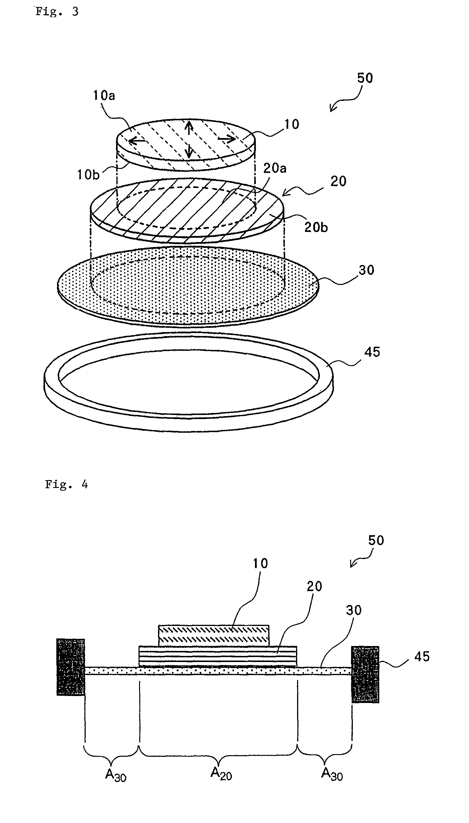
[0061]FIG. 3 is an exploded perspective view of a piezo-electric actuator of this embodiment, and FIG. 4 is a vertical sectional view of the piezo-electric actuator of FIG. 3.

[0062]As shown in FIGS. 3 and 4, piezo-electric actuator 50 of this embodiment comprises piezo-electric element 10 which serves as a driving source of vibration; seat 20 for supporting piezo-electric element 10; and vibration film 30 for supporting seat 20 in a configuration in which they are laminated in order. Piezo-electric element 10, seat 20, and vibration film 30 all have circularly shaped contours, and these three members are (concentrically) arranged such that they are centered at the same point. The outer periphery of vibration film 30 is connected to and supported by supporting member 45 which is formed in a circular frame shape.

[0063]More specifically, piezo-electric element 10 comprises a piezo-electric plate (piezo-electric ceramics) having two main surfaces 10a, 10b which oppose in parallel with e...

second embodiment

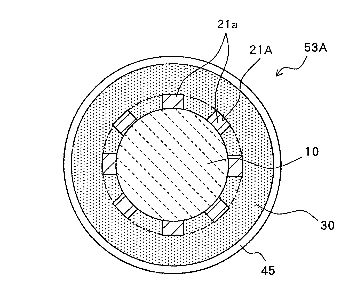
[0088]In the piezo-electric actuator of the present invention, a flection amount δ (m) of vibration film intervening section A between the outer periphery of the seat and the inner periphery of the supporting member can be calculated in the following manner. In this regard, vibration film intervening section A between the outer periphery of the seat and the inner periphery of the supporting member, i.e., vibration film intervening section A (30a) is an intervening site comprised of the vibration film positioned between outer periphery 20c of seat 20 and inter periphery 45a of supporting member 45, as shown in FIG. 7, and flection amount δ (m) of this vibration film intervening section A is calculated from the following calculation equation (1).

[0089]A description will be given of a method of calculating flection amount δ of vibration film intervening section A in the present invention. Calculation equation (1) described below is an equation applied to vibration film intervening sect...

third embodiment

[0102]The piezo-electric actuator of the present invention is not limited to those shown in the foregoing embodiments, but may have a configuration as shown in FIGS. 11A, 11B. FIG. 11A is an exploded perspective view showing the configuration of a piezo-electric actuator of a second embodiment, and FIG. 11B is a vertical sectional view of the piezo-electric actuator.

[0103]Piezo-electric actuator 51 of FIGS. 11A and 11B employs vibration film 31 which is formed with opening 31a at the center thereof. The rest of the configuration is similar to the first embodiment. Opening 31a is circular, and is formed to be concentric with piezo-electric element 10 and seat 20. Since opening 31a is formed, seat 20 is supported only around the outer periphery of its back surface (bottom surface as shown in the figure) by vibration film 31. Stated another way, the back surface of seat 20 has an area corresponding to opening 31a in an exposed state.

[0104]Even piezo-electric actuator 51 of this embodim...


PUM


Abstract

Piezo-electric actuator 50 of the present invention comprises piezo-electric element 10 for performing expansion / contraction motions in accordance with an electric field condition, seat 20 to which piezo-electric element 10 is adhered on at least one surface thereof, and supporting member 45 for supporting piezo-electric element 10 and seat 20, wherein piezo-electric element 10 and seat 20 vibrate up and down in accordance with the expansion / contraction motions of piezo-electric element 10. Seat 20 is connected to supporting member 45 through vibration 30 film which is less rigid than this seat 20.

Description

TECHNICAL FIELD[0001]The present invention relates to a piezo-electric actuator for generating vibrations using a piezo-electric element, and an electronic device using the same.BACKGROUND ART[0002]Conventionally, electromagnetic actuators have been utilized as driving sources for acoustic elements such as loud speakers and the like because of its ease of handling. The electromagnetic actuator comprises a permanent magnet and a voice coil, and generates vibrations by the action of a magnetic circuit of a stator using a magnet. An electromagnetic speaker, in turn, generates sound by vibrations of a lowly rigid vibration plate of an organic film or the like which is fixed to a vibration section of an electromagnetic actuator.[0003]Incidentally, the need for portable telephones and personal computers has increased in recent years, and associated therewith, small and power saving actuators have been increasingly demanded. However, since the electromagnetic actuator needs to apply a larg...

Claims


Application Information

Patent Timeline
Patent Type & Authority Patents(United States)
IPC IPC(8): H01L41/08
CPCB06B1/0651H01L41/0973H04R17/00G10K9/122H10N30/2047
Inventor ONISHI, YASUHARUSASAKI, YASUHIROTAKAHASHI, MASATAKEMORI, UKYOMURATA, YUKIO
Owner NEC CORP
Why Eureka
Try Eureka