Center splitter rake wheel structure for rakes

a splitter and rake technology, applied in the field of rakes, can solve the problems of affecting the spacing between the wheels is critical, and the wheels are prone to fighting each other, so as to reduce the ground pressure, and improve the life of the rake tin

Active Publication Date: 2012-12-04
VERMEER MFG CO
View PDF26 Cites 4 Cited by
  • Summary
  • Abstract
  • Description
  • Claims
  • Application Information

AI Technical Summary

Benefits of technology

[0010]The center splitter assembly is located in a position on the machine where space is limited. The present invention provides a solution that fits in the available space, allows the rake to fold to a transport orientation, while providing adequate performance by positioning each rake wheel with an effective raking distance that extends from the approximate center of the mount frame, to a distance away from the center.
[0011]In addition to drying material, lifting and turning the crop at that location can increase the efficiency of the baler / harvester to pick up the crop from the stubble. The splitter lifts the hay off the ground allowing the pickup on the baler to clean the ground better. This allows the baler operator to increase efficiency (drive faster, less crop loss). For the same reason, the splitter is also beneficial for crops that have been rained on causing them to lay closer / flatter to the ground.
[0014]The mounting of the rake wheel is important to good rake wheel life. The rake wheel “trails” behind the pivot point and slots on the mount allow the rake wheel to follow the ground and rise over bumps. This configuration also removes the need for suspension that is typical of wheel rakes. This mounting reduces ground pressure as the rake passes over the field. The latest test stand results show the splitter tines of the instant invention out live standard tines by over three times.
[0015]A major advantage of the mounting arrangement of the rake wheels on the center splitter of the present invention is that there is no need for suspension to obtain increased rake tine life. The center splitter rake wheels assembly of the present invention follows contour of ground, and when plugging starts to occur the wheels tend to lift, which prevents damage to the components.

Problems solved by technology

Since these rake wheels are attempting to move material in opposite directions, the spacing between the wheels has been found to be critical.
This, in turn, caused the wheels to fight each other and eventually stop rotating because the wheels pull in opposite directions.

Method used


Image

  • Center splitter rake wheel structure for rakes
  • Center splitter rake wheel structure for rakes
  • Center splitter rake wheel structure for rakes

Examples


Embodiment Construction

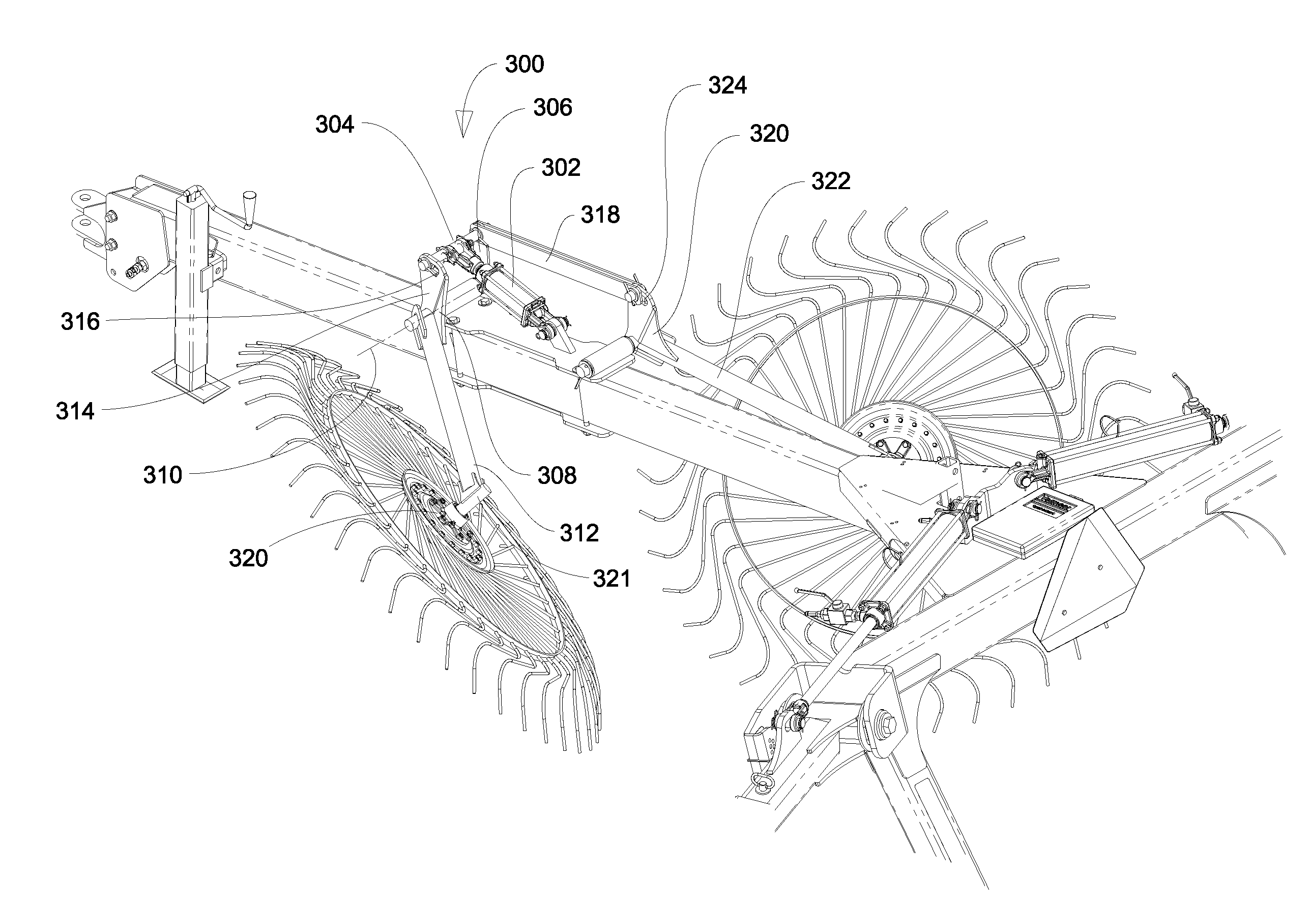
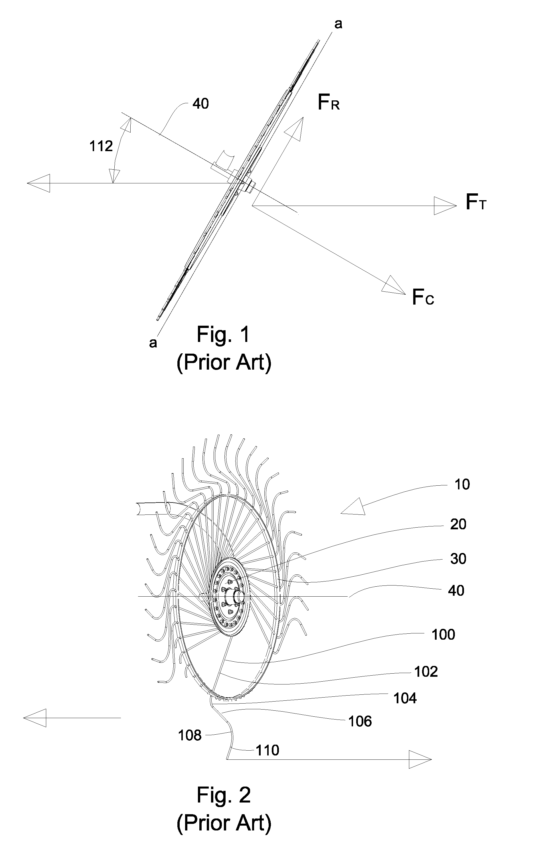
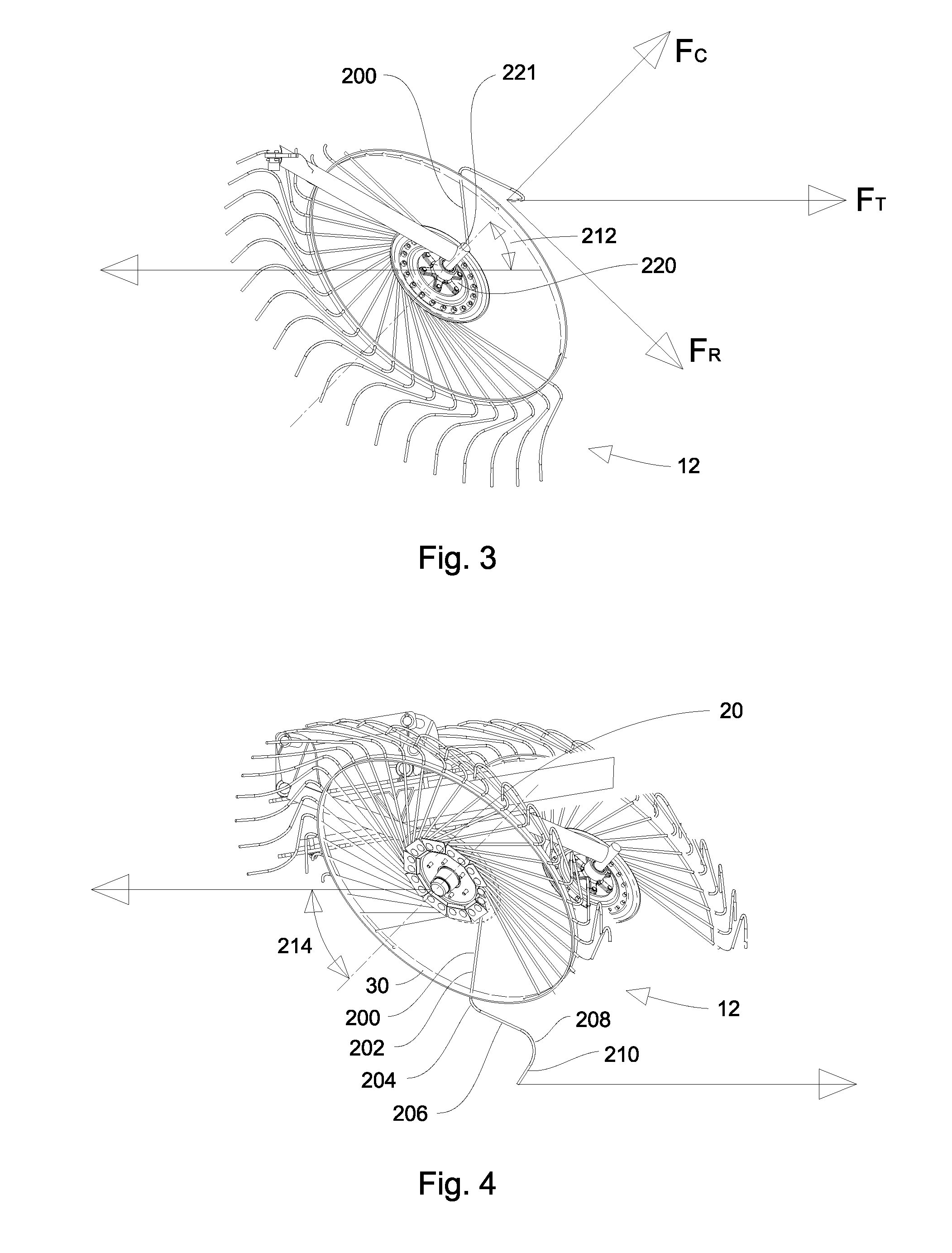
[0031]By changing the tine profile of a full sized rake wheel, and repositioning its orientation, this known configuration of a raking device can function in a constricted area, such as under the frame or under the tongue of the machine. The advantage of using a full sized wheel (for example, about 56 inch diameter) is to reduce crop wrapping under certain conditions when compared to a smaller diameter rake wheel.

[0032]The rake wheel is positioned at a compound angle which allows the tines to reach previously inaccessible areas, such as under tongues or frames. The tines of the rake wheel are bent to form an angle approximately perpendicular to the ground. This creates a dish shaped rake wheel. The result of tine profile allows the tines to drive the wheel and facilitate hay movement in constricted areas. A standard rake wheel in this position would cause the tines to passes over the crop without lifting and moving the crop. This present design is useful, when used as a pair, as a c...


PUM


Abstract

A pair of rake wheels in an assembly is referred to as a center splitter assembly. Each rake wheel is configured for free-rotation, meaning it is powered by contacting the ground. The center splitter is used to separate material, each wheel moving material in a different direction. The rake wheel on the left side of the center splitter assembly will rotate in a clockwise direction, as viewed from behind the wheel, which will cause the material to move from the right to the left. The opposite applies to the rake wheel on the right side of the center splitter assembly, where it will rotate counter-clockwise, moving material from the left to the right. Since these rake wheels are attempting to move material in opposite directions, the spacing between the wheels has been found to be critical.

Description

CROSS REFERENCE TO RELATED APPLICATIONS[0001]This application claims the benefit of U.S. Provisional Application Ser. No. 61 / 373,579 filed Aug. 13, 2010 entitled “Center Splitter for Rake” which is incorporated by reference herein in its entirety.STATEMENT REGARDING FEDERALLY SPONSORED RESEARCH OR DEVELOPMENT[0002]Not applicable.REFERENCE TO MICROFICHE APPENDIX[0003]Not applicable.BACKGROUND OF THE INVENTIONField of the Invention[0004]Various types of rakes are known to include a left side raking device, that moves material from the left to the middle, and a right side raking device, that moves material from the right to the middle, to form a windrow in the middle of the machine. These rakes are often referred to as V-Rakes, due to the configuration that has the shape of the letter “V”, when in the operating position. The windrows typically range from 2½ feet wide to 5 feet wide, typically being formed under the main frame of the raking device. The material lying on the ground in th...

Claims


Application Information

Patent Timeline
Patent Type & Authority Patents(United States)
IPC IPC(8): A01D76/00A01D78/00A01D80/00A01D84/00
CPCA01D78/144
Inventor MUNK, JESSE T.
Owner VERMEER MFG CO
Why Eureka
Try Eureka