Magnetron having a transparent cathode and related methods of generating high power microwaves

Active Publication Date: 2012-12-04
STC UNM
View PDF7 Cites 5 Cited by
  • Summary
  • Abstract
  • Description
  • Claims
  • Application Information

AI Technical Summary

Benefits of technology

[0016]Based on the various above-mentioned deficiencies of conventional magnetron designs, it may be desirable to improve upon conventional magnetron designs. For example, it may be desirable to provide a magnetron design th

Problems solved by technology

However, such an increase in thickness may lead to decreasing efficiency of the energy transfer.
Moreover, attempts to increase the efficiency and output power of a conventional magnetron by increasing the voltage and magnetic field (that retains the closeness of phase velocity of the operating wave and drift velocity of electrons, which is the necessary condition for microwave generation, and decreases the thickness of the electron flow) ultimately may lead to degradation of output characteristics.
This may occur because the azimuthal electric field of the operating wave, which is responsible for a capture of electrons to the anode, becomes too small.
It also may be difficult to generate long radiation pulse lengths with conv

Method used


Image

  • Magnetron having a transparent cathode and related methods of generating high power microwaves
  • Magnetron having a transparent cathode and related methods of generating high power microwaves
  • Magnetron having a transparent cathode and related methods of generating high power microwaves

Examples


Embodiment Construction

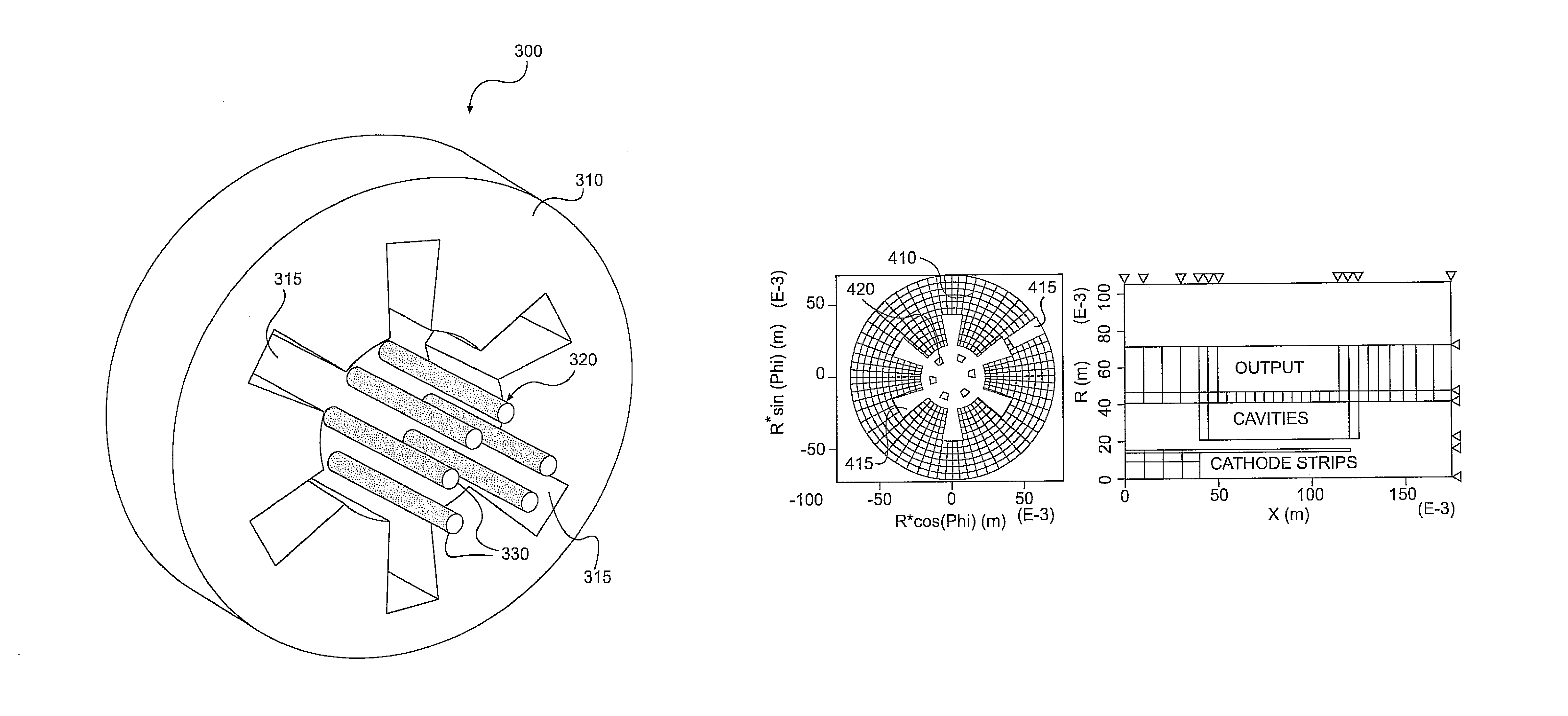
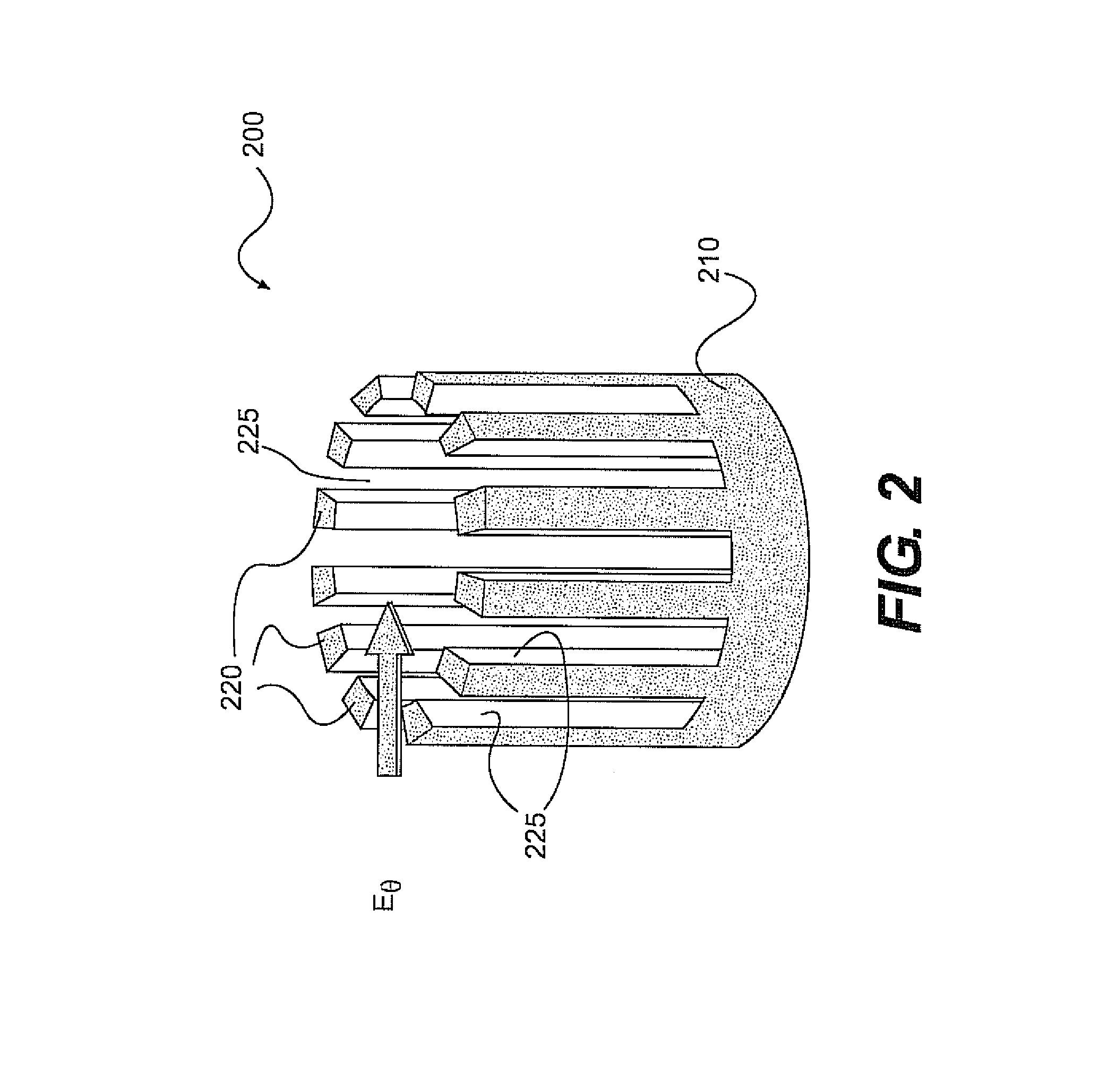
[0033]To achieve some of the advantages and desirable features noted above, the inventors discovered that by permitting the wave field in a conventional or relativistic magnetron to penetrate to the axis of the device so that significant azimuthal wave electric field in the electron flow formed around the cathode would be present to more rapidly transfer energy of the bunched electron flow to the electromagnetic field. The practical manifestation according to various exemplary embodiments includes replacing a solid cathode with separate longitudinally oriented emitters arranged on an imaginary cylindrical surface. For relativistic magnetrons, this can be realized, for example, by a hollow or tubular cold cathode, from which longitudinal strips are removed, thereby leaving a number of discrete emitters. The individual emitters can be evenly spaced, or grouped in bunches forming periodical emitter structures. Such cathodes according to exemplary aspects of the invention simultaneously...


PUM


Abstract

A cathode for use in a magnetron may include a plurality of longitudinally oriented emitter regions disposed around a longitudinal axis of the cathode. Each emitter region can be configured to emit electrons and adjacent emitter regions can be separated from one another by openings. The emitter regions can be configured to promote simultaneous cathode priming, magnetic priming, and electrostatic priming.

Description

CROSS-REFERENCE TO RELATED APPLICATIONS[0001]This application is a Continuation-In-Part of and claims the benefits of priority of U.S. Ser. No. 11 / 462,561, filed on Aug. 4, 2006, now U.S. Pat. No. 7,696,696, which claims the benefit of priority to U.S. Provisional Application No. 60 / 705,169, filed on Aug. 4, 2005, which are each incorporated by reference herein in their entirety.STATEMENT REGARDING FEDERALLY SPONSORED RESEARCH OR DEVELOPMENT[0002]This invention was made with Government support under Grant No. F49620-01-1-0354 and FA9950-05-1-0300, awarded by the Air Force Office of Scientific Research. The Government has certain rights in the invention.FIELD OF THE INVENTION[0003]The present invention relates generally to magnetrons and, more particularly, to novel cathodes to improve the performance of relativistic and conventional magnetrons.BACKGROUND OF THE INVENTION[0004]Magnetrons are widely used as powerful and compact sources for the generation of high power microwaves in a ...

Claims


Application Information

Patent Timeline
IPC IPC(8): H01J25/50
CPCH01J25/50
Inventor FUKS, MIKHAILSCHAMILOGLU, EDL
Owner STC UNM
Why Eureka
Try Eureka