
System and method of auto-exposure control for image acquisition hardware using three dimensional information

an image acquisition hardware and auto-exposure control technology, applied in the field of system and method of auto-exposure control of image acquisition hardware using three dimensional information, can solve problems such as attempts to make machine vision applications, and achieve the effect of sufficient grayscale information

Active Publication Date: 2012-12-04
COGNEX TECH & INVESTMENT
View PDF157 Cites 28 Cited by
  • Summary
  • Abstract
  • Description
  • Claims
  • Application Information

AI Technical Summary

Benefits of technology

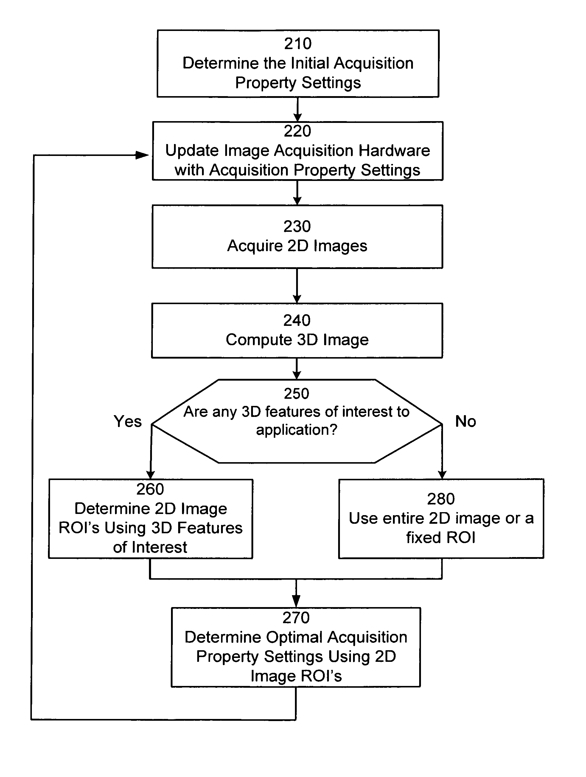
[0013]By performing auto-exposure analysis over the region of interest as determined from 3D analysis of the acquired images, the acquisition property settings can be assigned such that the light levels within the region of interest fall within the linear range, producing sufficient grayscale information for identifying particular objects and profiles in subsequently acquired images. For example, in a machine vision application that detects people passing through a doorway, the region of interest can be the portion of the 2D image that generates 3D features of a head and shoulders profile within a 3D model of the doorway scene. With higher quality images, more accurate detection of people candidates within the monitored scene results.

Problems solved by technology

As a consequence, machine vision applications that attempt to locate or detect particular objects with imaging characteristics that differ from the rest of the scene and / or that are not a dominant portion of the scene, can suffer due to a lack of sufficient grayscale information for the objects of interest.

Method used


Image

  • System and method of auto-exposure control for image acquisition hardware using three dimensional information
  • System and method of auto-exposure control for image acquisition hardware using three dimensional information
  • System and method of auto-exposure control for image acquisition hardware using three dimensional information

Examples


Embodiment Construction

[0027]A description of preferred embodiments of the invention follows.

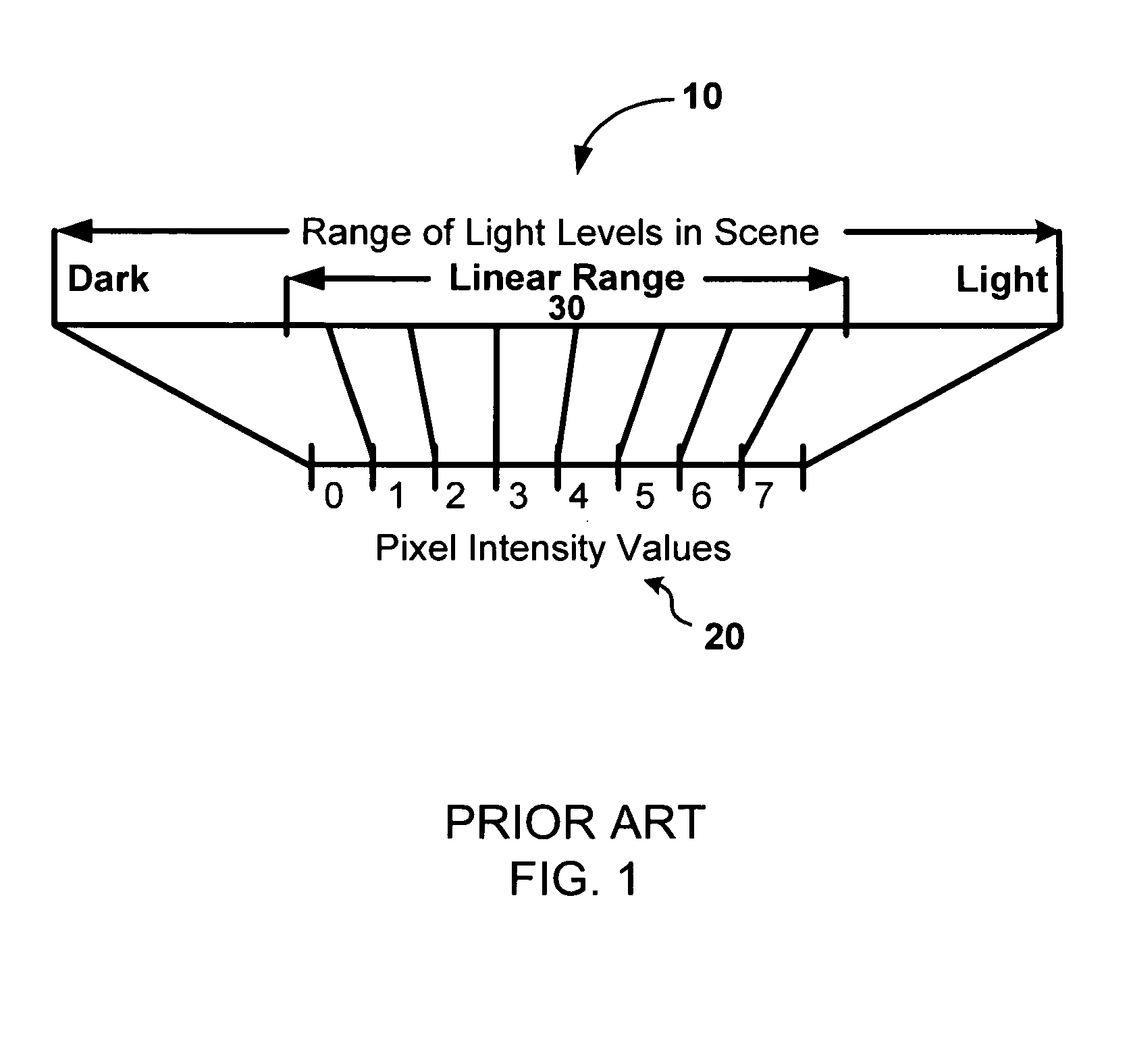
[0028]Machine vision applications are directly affected by a sensor's ability to linearly represent the light levels of the objects of interest in the scene being acquired. Ideally, the linear range is adjusted so its dark end includes the light levels from the darkest objects of interest and its bright end includes the light levels from the brightest objects of interest.

[0029]For many applications, where the light level is static, the linear range can be adjusted once by configuring the acquisition property settings of the image acquisition hardware and then used indefinitely. For other applications, where the ambient light level is not static or the reflectivity of the objects of interest is changing, the linear range must be adjusted dynamically. The most difficult applications are those with changing ambient light levels, changing reflectivity of the objects of interest, and where the objects of interest are m...


PUM


Abstract

A system and method of auto-exposure control is provided for image acquisition hardware using three dimensional information to identify a region(s) of interest within an acquired 2D image or images upon which to apply traditional auto-exposure techniques. By performing auto-exposure analysis over the region of interest, the acquisition property settings can be assigned such that the light levels within the region of interest fall within the linear range, producing sufficient grayscale information for identifying particular objects and profiles in subsequently acquired images. For example, in a machine vision application that detects people passing through a doorway, the region of interest can be the portion of the 2D image that generated 3D features of a head and shoulders profile within a 3D model of the doorway scene. With higher quality images, more accurate detection of people candidates within the monitored scene results.

Description

RELATED APPLICATION[0001]This application is a continuation-in-part of U.S. application Ser. No. 10 / 702,059, filed Nov. 5, 2003. The entire teachings of the above application are incorporated herein by reference.BACKGROUND OF THE INVENTION[0002]Imaging sensors are light sensitive devices that convert light into electrical charges. Imaging sensors used in most digital imaging systems are charge-coupled devices (CCD) or complementary metal oxide semiconductor (CMOS) devices. These devices are typically composed of an array of light sensitive diodes called pixels that convert photons into electrons when exposed to light. The electrical charge that accumulates at each pixel on the imaging sensor array is proportional to the brightness of the light that reaches the pixel during the period of exposure. An electrical signal output from the device represents the collection of charges from the pixels and is used to generate an image.[0003]Commercially available CCD and CMOS sensors have a li...

Claims


Application Information

Patent Timeline
IPC IPC(8): G06K9/00
CPCG06K9/00778G06T7/0075G07C9/00G07C9/025G06T7/204G06T7/2086H04N5/2351H04N13/0296G06T2207/30201G06T7/593G06T7/248G06T7/285H04N13/296G07C9/15G06V20/53H04N23/71
Inventor MARRION, JR., CYRIL C.NICHANI, SANJAY
Owner COGNEX TECH & INVESTMENT
Learn More