Check patentability & draft patents in minutes with Patsnap Eureka AI!

Combined cycle powered generating plant having reduced start-up time

a technology of generating plant and cycle, which is applied in the direction of steam engine plant, machine/engine, mechanical equipment, etc., can solve the problems of high-temperature section melting, damage to gas turbine, and time-consuming heating, and achieve the effect of reducing the start-up tim

Active Publication Date: 2012-12-11
MITSUBISHI POWER LTD
View PDF17 Cites 2 Cited by
  • Summary
  • Abstract
  • Description
  • Claims
  • Application Information

AI Technical Summary

Benefits of technology

This approach significantly shortens the start-up time of the combined cycle power generating plant by warming both steam pipes concurrently and reducing the steam supply capacity needs, thereby enhancing operational efficiency and durability of the gas turbine components.

Problems solved by technology

However, when the temperature of the combustion gas at the inlet is high, there is a concern that damage and melting of the high-temperature section of the gas turbine (for example, the combustor, the gas turbine stator blades, and the gas turbine rotor blades and the like) may occur due to the heat of the combustion gas.
However, in the method in which the steam system is warmed simply by channeling steam in sequence from the upstream side of the cooling steam system, there are problems in that the warming takes time, and thus the start-up of the gas turbine plant (i.e., combined cycle power generating plant) takes time.

Method used


Image

  • Combined cycle powered generating plant having reduced start-up time
  • Combined cycle powered generating plant having reduced start-up time
  • Combined cycle powered generating plant having reduced start-up time

Examples


first embodiment

[0055]Below, a combined cycle power generating plant according to a first embodiment of the present invention will be explained with reference to FIG. 1 to FIG. 5.

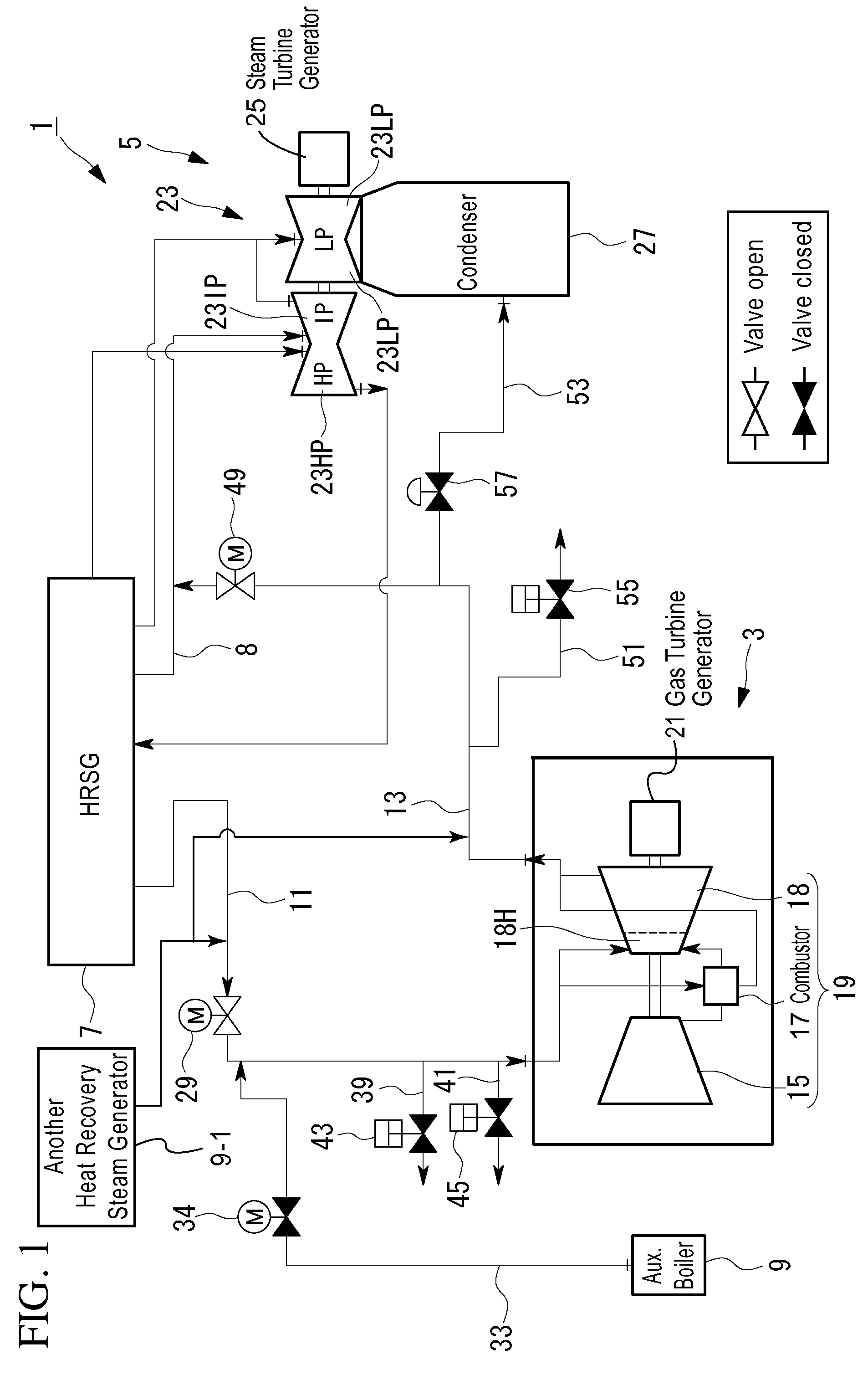
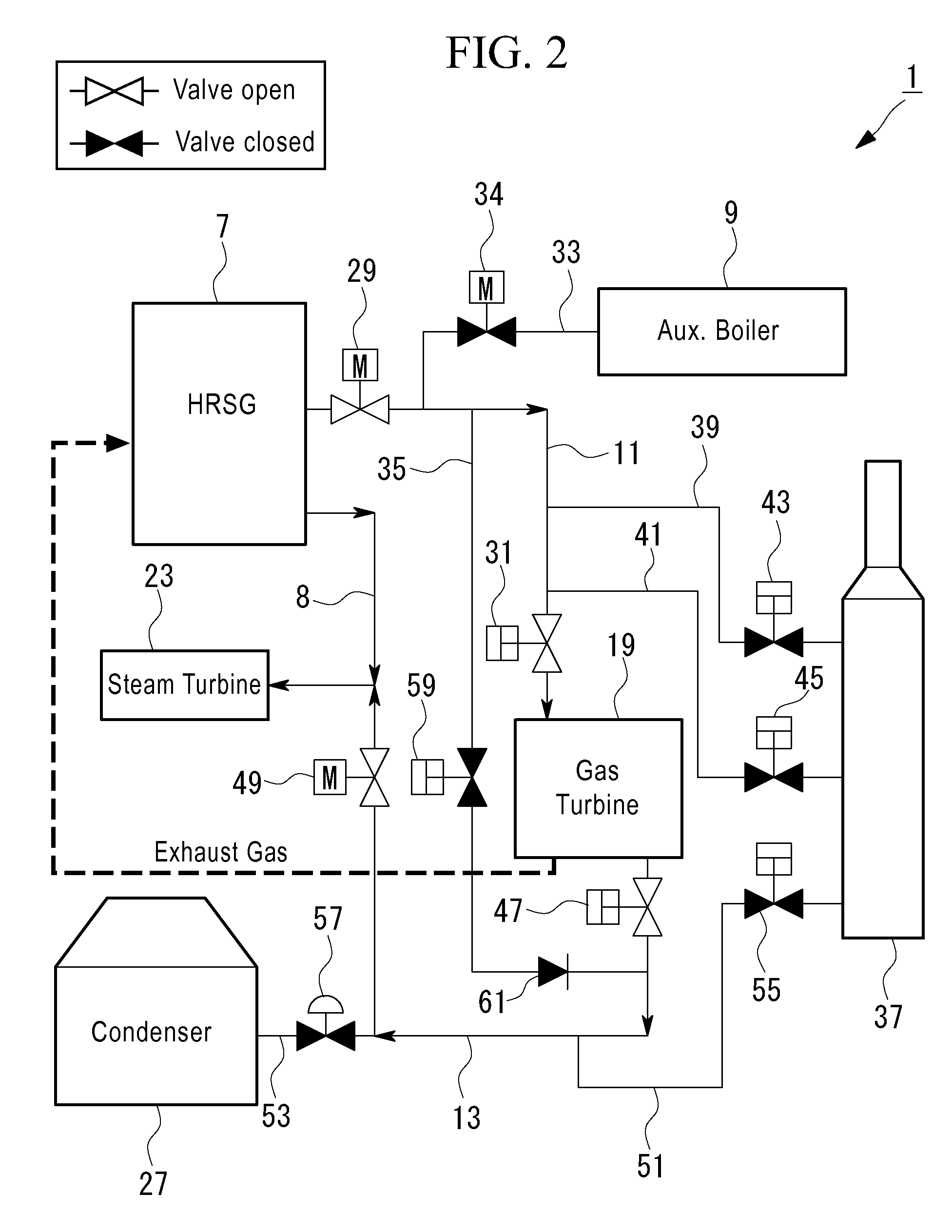
[0056]FIG. 1 is a schematic diagram for explaining the basic structure of the combined cycle power generating plant of the present embodiment.

[0057]As shown in FIG. 1, the combined cycle power generating plant 1 is provided with a gas turbine power generating section 3 that is provided with a gas turbine 19, a steam turbine power generating section 5 that is provided with a steam turbine 23, a heat recovery steam generator (boiler) 7 and an auxiliary boiler (steam supplying section) 9 that supply steam, and a first pipe 11 and a second pipe 13 that direct the steam.

[0058]The gas turbine power generating section 3 is one in which a gas turbine 19, which uses liquefied natural gas or the like as a fuel, is rotated, and the resulting rotational drive force is used to carry out power generation. As shown in FIG. 1, the gas tur...

second embodiment

[0120]Next, a second embodiment of the present invention will be explained with reference to FIG. 6 to FIG. 8.

[0121]The basic structure of the combined cycle power generating plant of the present embodiment is similar to that of the first embodiment. However, the method of warming the first and second steam pipes differs from that of the first embodiment. Thus, in the present embodiment, only the structure related to the warming of the first and second steam pipes will be explained with reference to FIG. 6 to FIG. 8, and the explanations of the other structural elements and the like will be omitted.

[0122]FIG. 6 is a schematic diagram for explaining the combined cycle power generating plant of the present embodiment.

[0123]Note that the structural elements that are identical to those of the first embodiment have identical reference numerals appended thereto, and the explanations thereof will be omitted.

[0124]As shown in FIG. 6, the combined cycle power generating plant 101 is provided...

third embodiment

[0146]Next, a third embodiment of the present invention will be explained with reference to FIG. 9 and FIG. 10.

[0147]The basic structure of the combined cycle power generating plant of the present embodiment is similar to that of the first embodiment. However, the start-up method of the gas turbine power generating section is different from that of the first embodiment. Thus, in the present embodiment, only the structures related to the start-up of the gas turbine power generating section will be explained with reference to FIG. 9 and FIG. 10, and the explanations of the other structural elements and the like will be omitted.

[0148]FIG. 9 is a schematic diagram for explaining the combined cycle power generating plant according to the present embodiment.

[0149]Note that the structural elements that are identical to those of the first embodiment have identical reference numerals appended thereto, and the explanations thereof will be omitted.

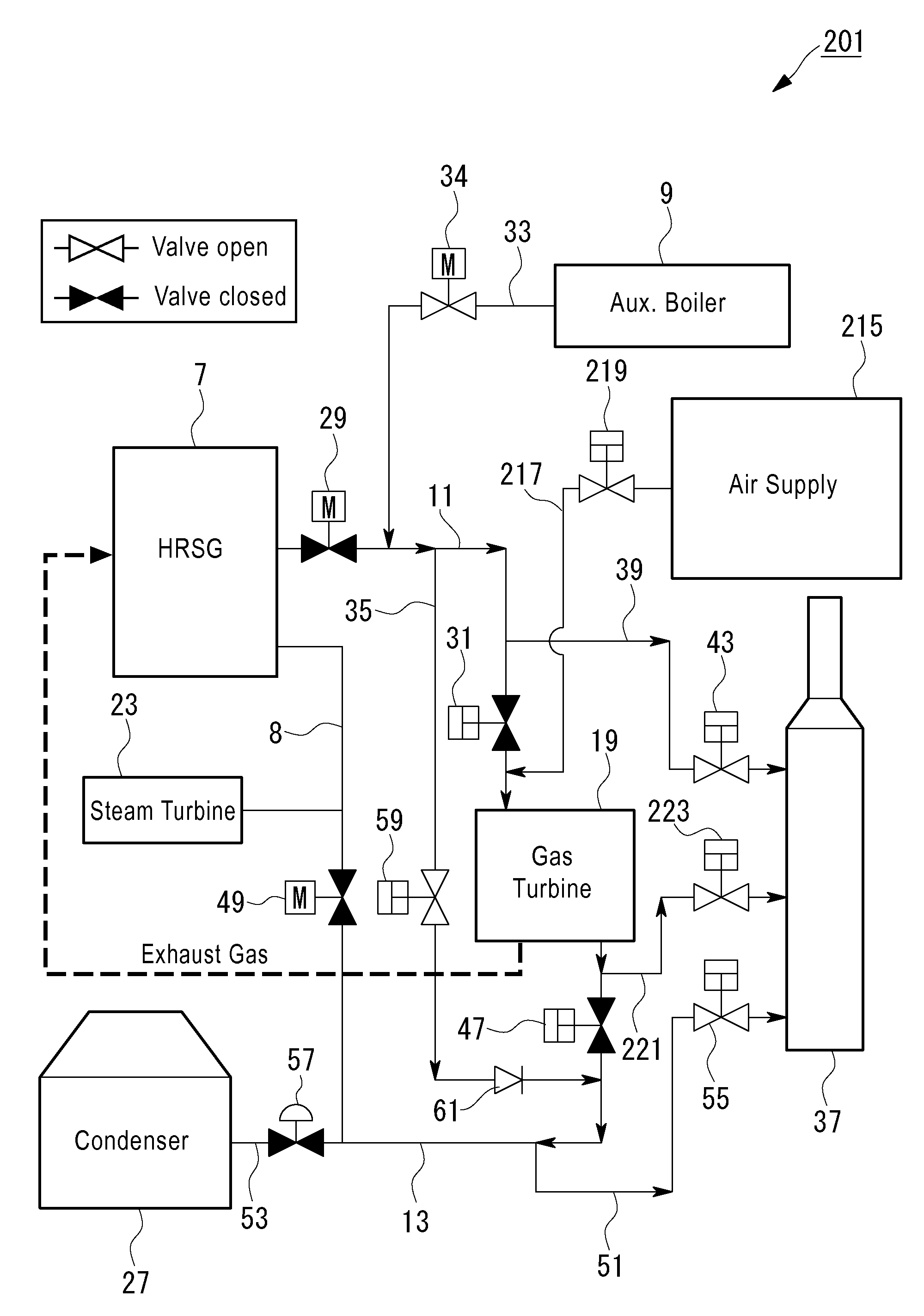
[0150]As shown in FIG. 9, a combined cycle pow...


PUM


Abstract

A combined cycle power generating plant that can realize a reduction in the start-up time includes a gas turbine, a steam turbine, a steam supplying section that supplies steam to the gas turbine, a first steam pipe that directs steam from the steam supplying section to the gas turbine, a second steam pipe that directs steam from the gas turbine to the steam turbine, a first release section that carries out control such that the supply destination of steam that is directed to the first steam pipe is one of either the outside of the gas turbine or the outside of the first steam pipe, a second release section that carries out control such that the supply destination of steam that is directed to the second steam pipe is one of either the outside of the steam turbine or the outside of the second steam pipe, and a bypass pipe that directs at least a portion of the steam inside the first steam pipe to the second steam pipe between the gas turbine and the second steam pipe.

Description

BACKGROUND OF THE INVENTION[0001]1. Field of the Invention[0002]This application is based on Japanese Patent Application No. 2007-088748, the content of which is incorporated herein by reference.[0003]The present invention relates to a combined cycle power generating plant.[0004]2. Description of Related Art[0005]In recent years, thermal power plants that use liquefied natural gas and the like as a fuel have come to be widely used. A combined cycle power generating plant that is provided with a gas turbine plant and a steam turbine plant is widely used as such a thermal power plant.[0006]In the combined cycle power generating plant described above, first, a gas turbine drives a generator to generate power. Simultaneously, in a heat recovery steam generator, the heat (exhaust heat) that has been discharged from the gas turbine generates steam by evaporating condensed water that has been supplied from a condenser. Steam that is thereby generated is supplied to the steam turbine and th...

Claims


Application Information

Patent Timeline
Patent Type & Authority Patents(United States)
IPC IPC(8): F01K13/02
CPCF01K13/02F01K21/047F01K23/106F02C6/18Y02E20/16
Inventor KITAGUCHI, YOSHINORI
Owner MITSUBISHI POWER LTD
Features
  • R&D
  • Intellectual Property
  • Life Sciences
  • Materials
  • Tech Scout
  • Unparalleled Data Quality
  • Higher Quality Content
  • 60% Fewer Hallucinations
Learn More