Transport-object transporting device and image processing apparatus
a technology of image processing apparatus and transport object, which is applied in the direction of transportation and packaging, electrographic process, instruments, etc., can solve the problems of increasing the cost of the sheet transporting device, shortening the transport path, and becoming smaller in size, and achieves high accuracy
- Summary
- Abstract
- Description
- Claims
- Application Information
AI Technical Summary
Benefits of technology
Problems solved by technology
Method used
Image

Examples
first embodiment
FIGS. 1 to 28
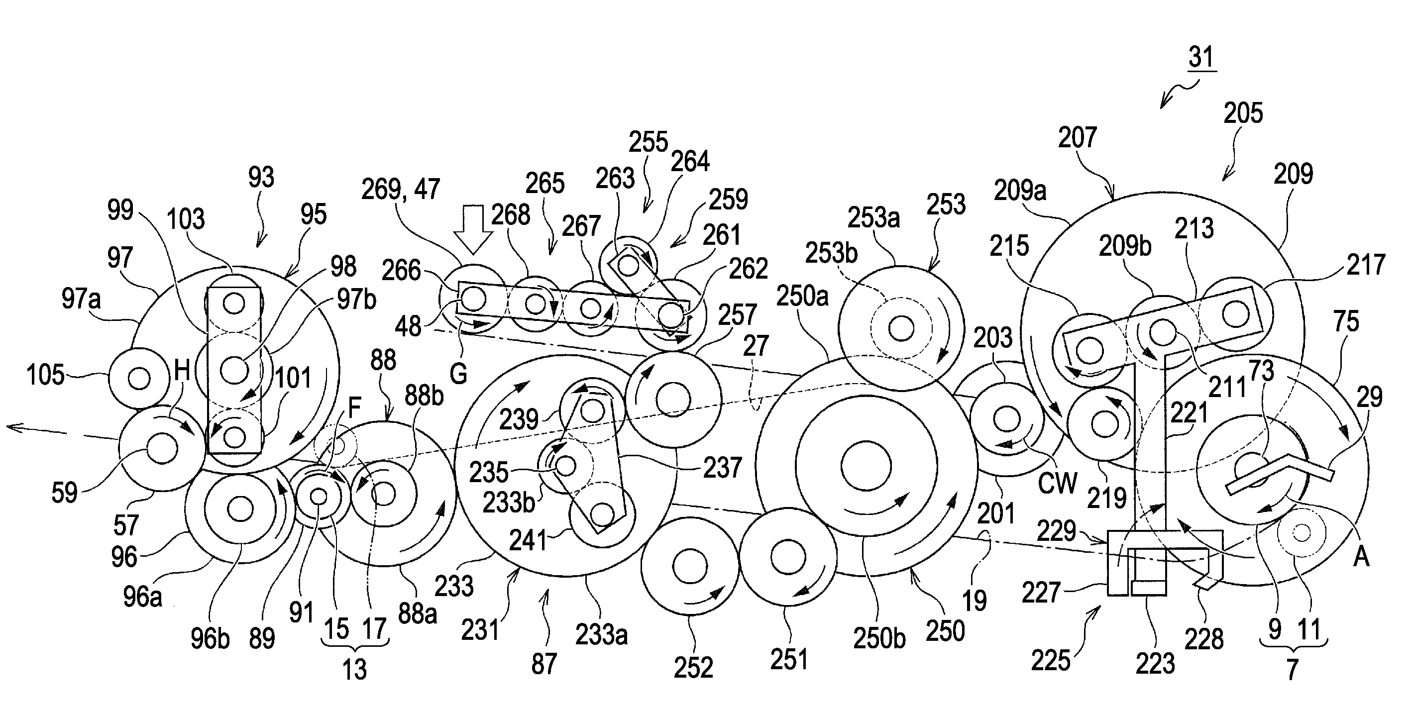
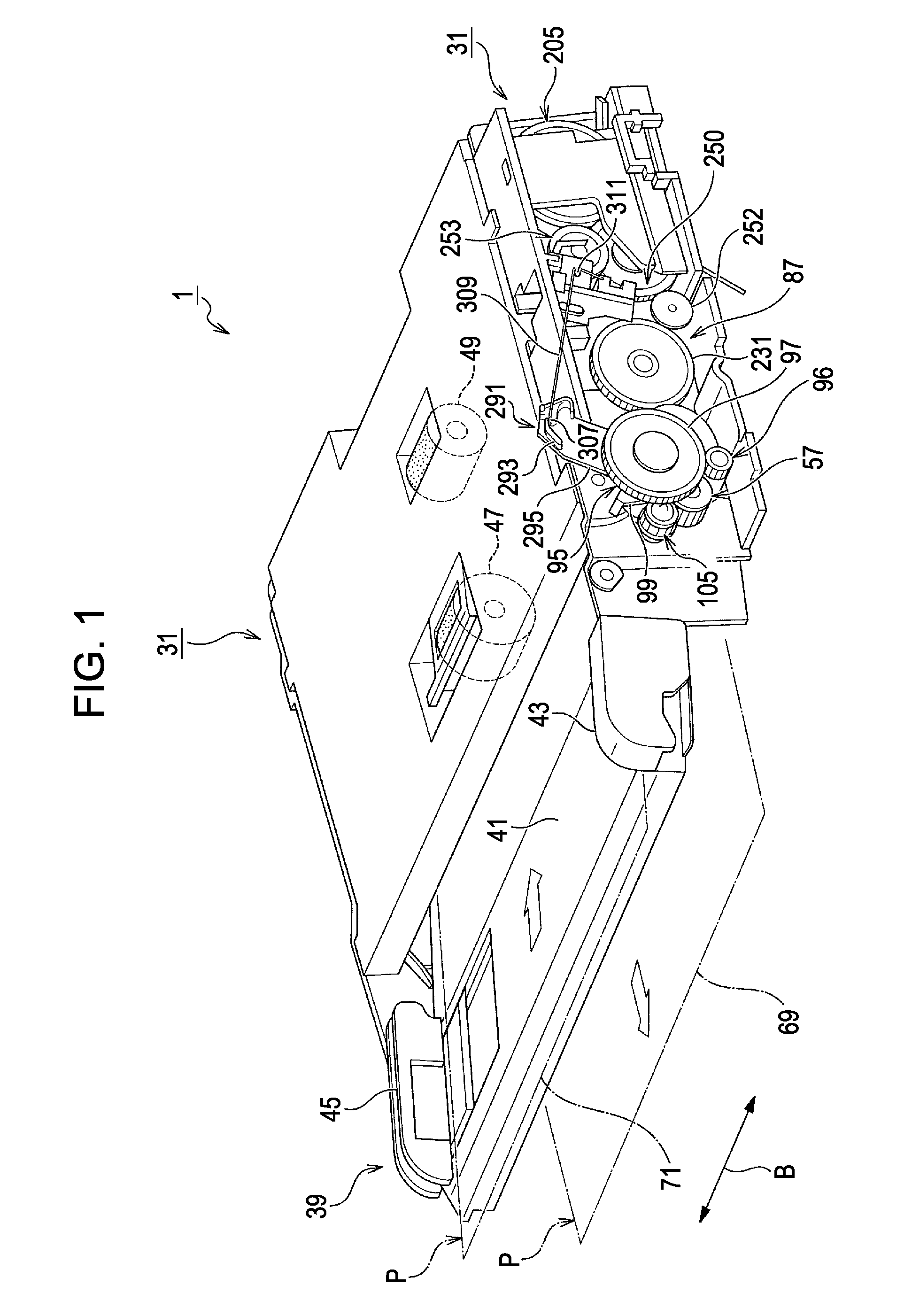
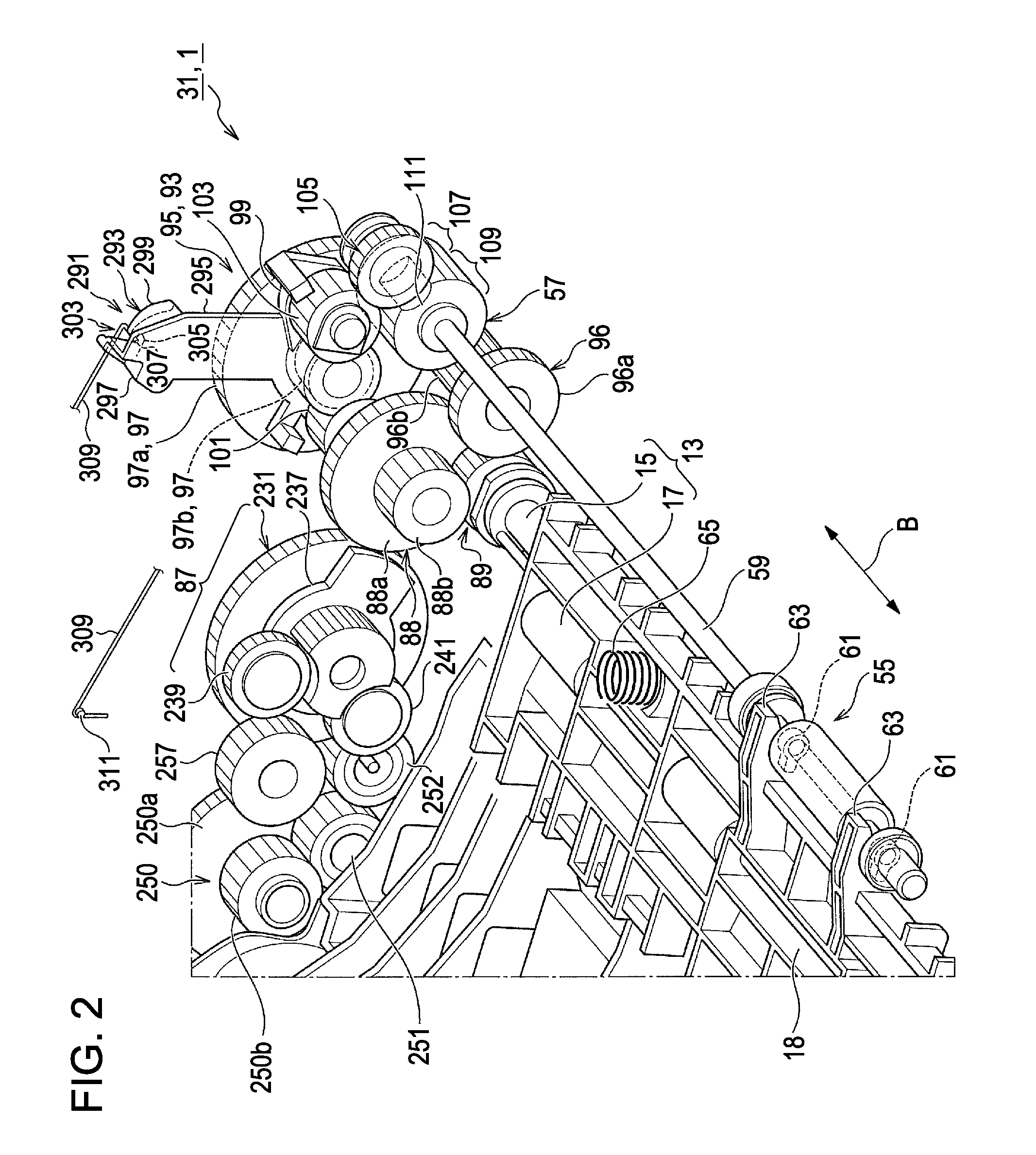
[0074]The scanner 1 is capable of loading therein a sheet transporting device 31 according to an embodiment to be described below. The sheet transporting device 31 includes a driving motor 201 capable of rotating in forward and reverse directions, a feed roller 47 that rotates in a feeding direction G so as to feed sheets P set on the feed tray 39 in a one-by-one fashion, a transport roller 7 that rotates in a transporting direction A so as to transport the sheet P on the transport path 19, a discharge roller 13 switchable between a nip position and a release position and configured to rotate in a discharging direction E to discharge the sheet P from the transport path 19 or rotate in an entry direction F to send the sheet P to the transport roller 7 via the inversion path 27, and a nip-release switching mechanism 55 that switches the discharge roller 13 between the nip position and the release position in accordance with a rotational position of a cam driving gear 57.
[...
second embodiment
[0177]A second embodiment of the invention will now be described with reference to FIG. 29.
[0178]For example, in the case of the first embodiment, trigger operation for reactivating the cam driving gear 57 from a stopped state is necessary after the image processor 35 starts to read image information. The trigger operation is performed by switching the rotating direction of the driving motor 201 from the forward direction CCW to the reverse direction CW. Therefore, when performing the trigger operation, a non power transmission state in which the first planetary gear 215 to the second planetary gear 217 of the transport planetary-gear mechanism 207 move away from the transport-roller driving gear 75 to the intermediate gear 219 occurs.
[0179]Accordingly, when the rotating direction of the driving motor 201 is switched back to the forward direction CCW after the trigger operation, the number of steps of the driving motor 201 detected by the rotary encoder or the like sometimes does no...
third embodiment
[0183]A third embodiment of the invention will now be described with reference to FIG. 31.
[0184]As an alternative to the first embodiment in which the engaging portion 307 is a rod-like member formed integrally with the elastic support rod 309, the engaging portion 307 and a member that applies a bias force to the engaging portion 307 may be formed as separate components. Specifically, a power-transmission blocking mechanism 291B shown in FIG. 31 may be formed by providing the engaging portion 307 at a terminal end331a of a rocking lever 331 that rocks about a rocking shaft 329, providing a latching hook 333 at a base end 331b of the rocking lever 331, providing a latching hook 337 in a support frame 335 of a sheet transporting device 31B, and providing a bias member 339 formed of, for example, an extension coil spring between the two latching hooks 333 and 337.
[0185]The power-transmission blocking mechanism 291B having such a configuration can exhibit the same effects and the same ...
PUM
| Property | Measurement | Unit |
|---|---|---|
| length | aaaaa | aaaaa |
| length | aaaaa | aaaaa |
| length | aaaaa | aaaaa |
Abstract
Description
Claims
Application Information
 - R&D
- Intellectual Property
- Life Sciences
- Materials
- Tech Scout
- Unparalleled Data Quality
- Higher Quality Content
- 60% Fewer Hallucinations
Browse by: Latest US Patents, China's latest patents, Technical Efficacy Thesaurus, Application Domain, Technology Topic, Popular Technical Reports.
© 2025 PatSnap. All rights reserved.Legal|Privacy policy|Modern Slavery Act Transparency Statement|Sitemap|About US| Contact US: help@patsnap.com