
Slidable sheaths for tissue removal devices

a tissue removal and sliding technology, applied in the field of medical devices and methods for removing tissue, can solve the problems of disc tissue irreparably damaged, unintentional removal of healthy bone tissue, and injuring spinal tissue during use, so as to minimize movement of the probe, prevent or minimize damage to non-target tissue, and minimize the effect of abutting the distal end of the probe against the tissu

Active Publication Date: 2012-12-11
BOSTON SCI SCIMED INC
View PDF33 Cites 3 Cited by
  • Summary
  • Abstract
  • Description
  • Claims
  • Application Information

AI Technical Summary

Benefits of technology

The present invention provides a tissue removal device that can be used to remove tissue from a patient. The device includes a tubular member with a tissue removal element mounted on a drive shaft. The device can be rigid, semi-rigid, or flexible. A sheath is slidably disposed over the probe to protect adjacent tissue from the moving probe. The sheath can bend without an external force to minimize damage to non-target tissue. The probe can have a window through which the tissue removal element is exposed to further minimize damage to non-target tissue. The method involves placing a sheath between target and non-target tissue and sliding the sheath and probe relative to each other to expose the tissue removal element in contact with the target tissue. The sheath can be bent to guide the probe and minimize damage to non-target tissue. The technical effects of the invention include minimizing damage to non-target tissue, reducing the risk of complications, and improving the precision of tissue removal procedures.

Problems solved by technology

In some cases, however, the disc tissue is irreparably damaged, in which case, surgery is the best option.
A physician may have difficulty controlling existing bone removal devices, however, and may unintentionally remove healthy bone tissue or injure spinal tissue during use.
This problem is exacerbated with percutaneous treatments, which, although less invasive than other procedures, limit the range of motion of the cutting instrument, thereby further limiting the control that the physician may have during the bone cutting procedure.
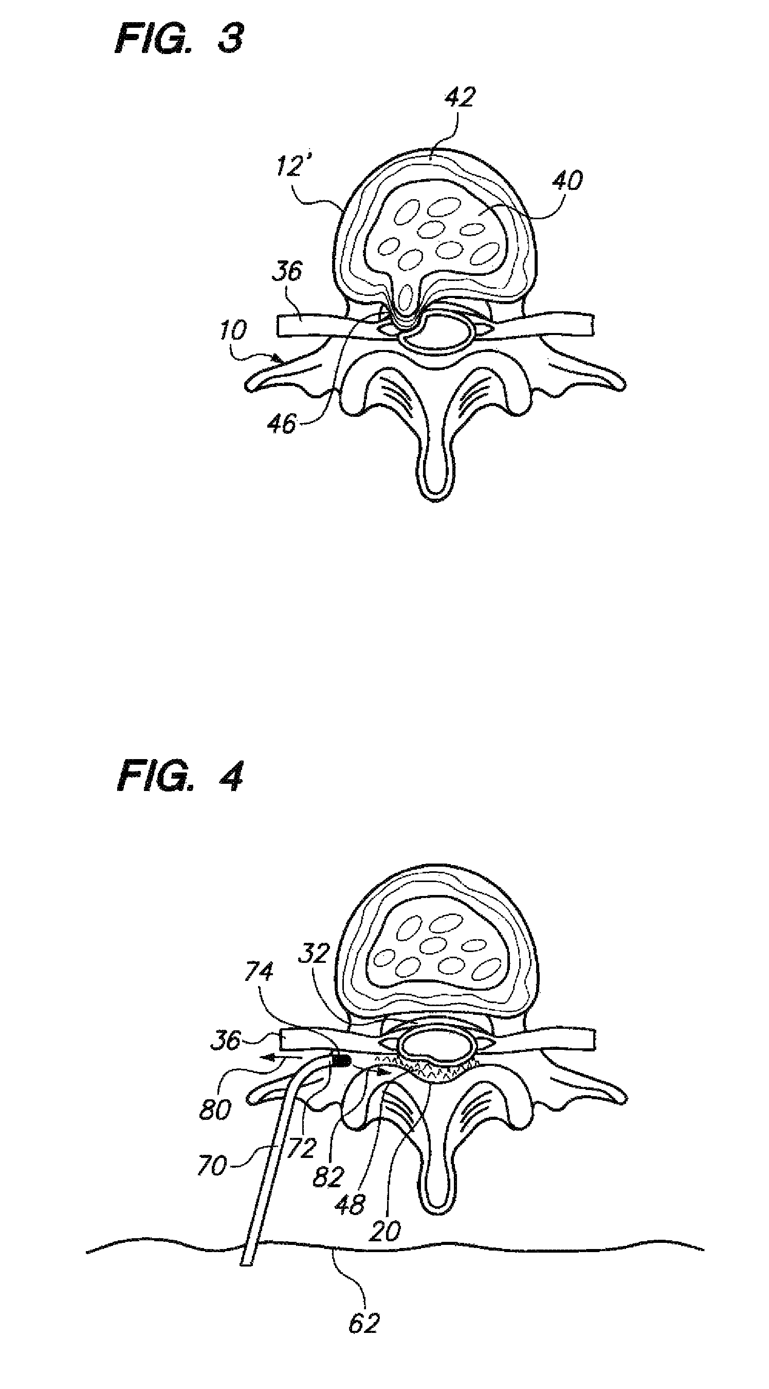
However, because of the close proximity between the burr 74 and the nerve root 36, there is a significant risk that the burr 74, if improperly positioned, may accidentally injure the nerve root 36 during such procedure.

Method used


Image

  • Slidable sheaths for tissue removal devices
  • Slidable sheaths for tissue removal devices
  • Slidable sheaths for tissue removal devices

Examples


Embodiment Construction

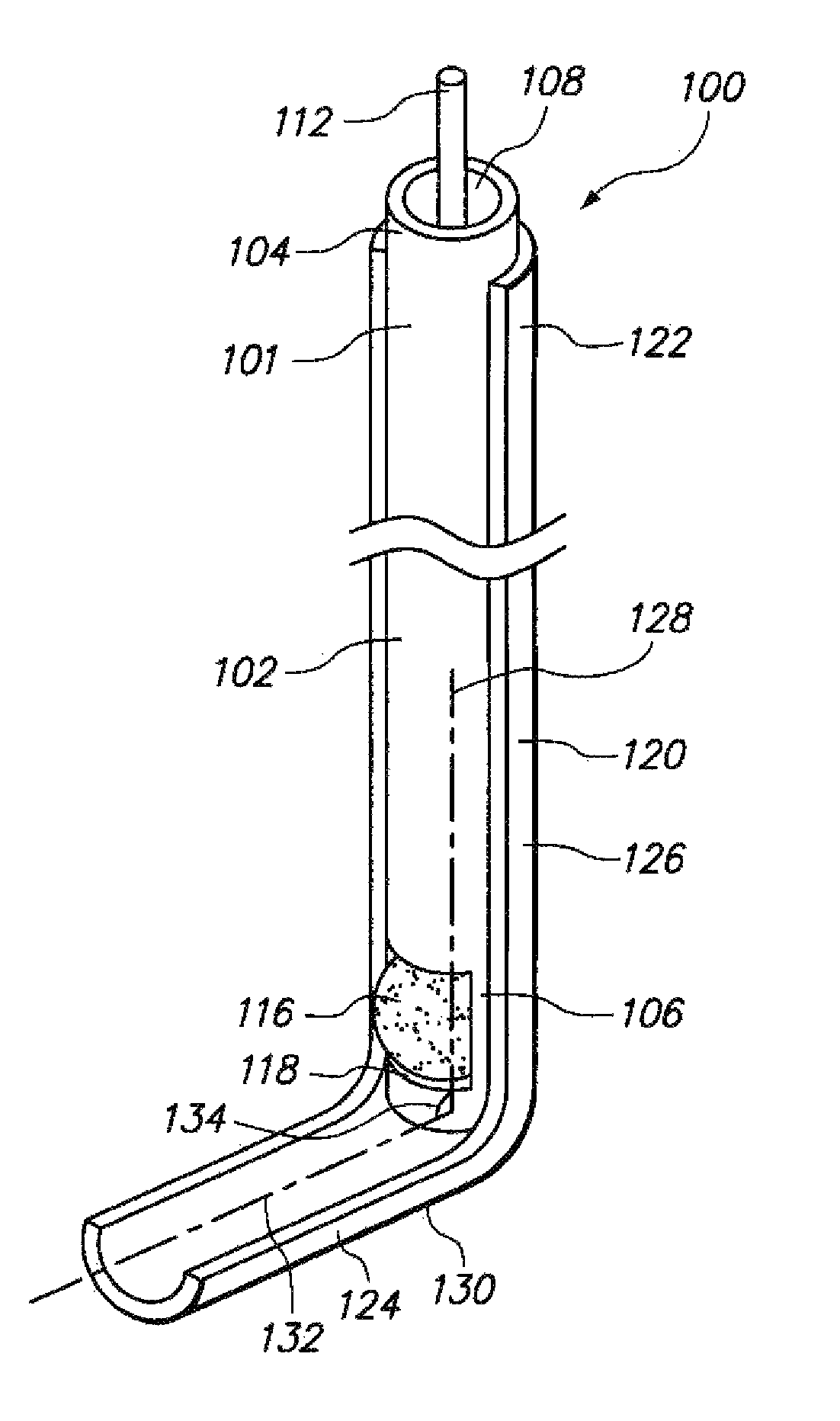
[0032]FIGS. 5A and 5B illustrate a tissue removal device 100 constructed in accordance with a preferred embodiment of the invention. The device 100 includes a tissue removal probe 101 and a sheath 120 placed circumferentially around the probe 101. The sheath 120 is configured to be placed between tissue to be protected and the probe 101 to prevent the probe 101 from rubbing and abrading the tissue during use, thereby protecting the tissue from the probe 101.

[0033]The tissue removal probe 101 includes a tube (a tubular member) 102, a tissue removal element 116, and a drive shaft 110. The tube 102 has a proximal end 104, a distal end 106, and a lumen 108 extending between the proximal and the distal ends 104, 106. The tube 102 also has an opening (cutting window) 118 through a wall of the tube 102 at the distal end 106. In the illustrated embodiment, the tube 102 has a relaxed configuration that is substantially rectilinear. Alternatively, a portion (e.g., the distal end 106) of the t...


PUM


Abstract

A tissue removal device and method of using the device to remove tissue from a patient is provided. The tissue removal device comprises a tissue removal probe and a sheath slidable relative to the probe. The probe has a tissue removal element, and the sheath has a portion that exposes the tissue removal element. The sheath distal end may be pre-shaped to bend when slid distal to the probe. The probe may have a window through which the tissue removal element is exposed.

Description

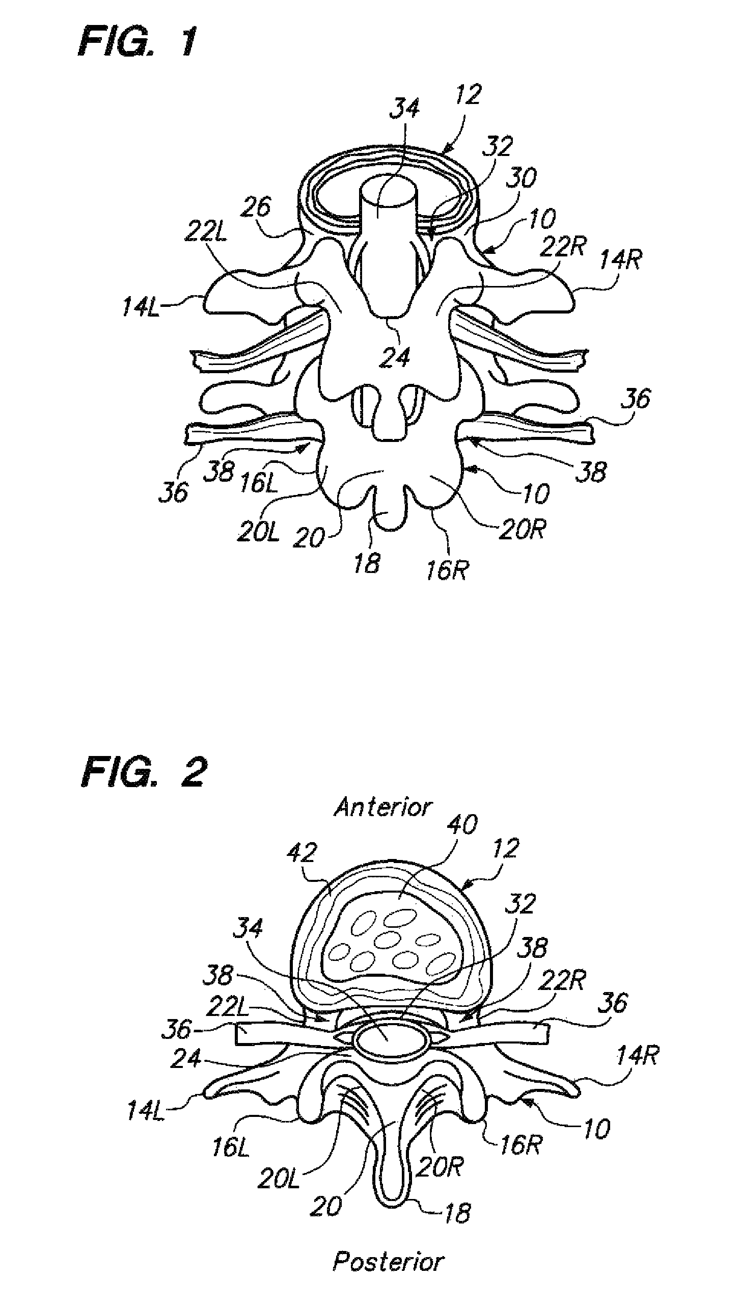
FIELD OF THE INVENTION[0001]The field of the invention pertains to medical devices and methods for removing tissue, and in particular, vertebral bone and intervertebral disc tissue.BACKGROUND OF THE INVENTION[0002]The spinal column consists of thirty-three bones called vertebra, the first twenty-four vertebrae of which make up the cervical, thoracic, and lumbar regions of the spine and are separated from each other by “pads” of tough cartilage called “intervertebral discs,” which act as shock absorbers that provide flexibility, stability, and pain-free movement of the spine.[0003]FIGS. 1 and 2 illustrate a portion of a healthy and normal spine, and specifically, two vertebra 10 and two intervertebral discs 12 (only one shown). The posterior of the vertebra 10 includes right and left transverse processes 14R, 14L, right and left superior articular processes 16R, 16L, and a spinous process 18. Muscles and ligaments that move and stabilize the vertebra 10 are connected to these structu...

Claims


Application Information

Patent Timeline
Patent Type & Authority Patents(United States)
IPC IPC(8): A61B17/00
CPCA61B17/1633A61B17/1671A61B17/32002A61B17/320783A61B17/3496A61B2017/00261A61B2017/320004A61B2019/4805A61B2019/481A61B2090/0801A61B2090/08021
Inventor PATEL, MUKUNDCARRISON, HAROLD F.
Owner BOSTON SCI SCIMED INC
Learn More