Heat transfer compositions

a technology of compositions and heat, applied in the field of heat transfer compositions, can solve the problems of excessive flammability of r-152a, and reduced flammability of r-152a

Inactive Publication Date: 2012-12-18
MEXICHEM AMANCO HLDG DE C V
View PDF116 Cites 26 Cited by
  • Summary
  • Abstract
  • Description
  • Claims
  • Application Information

AI Technical Summary

Problems solved by technology

Due to international concern that fully and partially halogenated chlorofluorocarbons were damaging the earth's protective ozone layer, there was general agreement that their manufacture and use should be severely restricted and eventually phased out completely.
However the flammability of R-152a is judged too high, for example to permit its safe use in mobile air conditioning systems.
In particular it is believed that its lower flammable limit in air is too low, its flame speeds are too high, and its ignition energy is too low.
Fluorocarbon combustion chemistry is complex and unpredictable.
It is not always the case that mixing a non flammable fluorocarbon with a flammable fluorocarbon reduces the flammability of the fluid.
A consequence of this is that to use R-1234yf and achieve energy efficiency and cooling performance equivalent to R-134a, increased complexity of equipment and increased size of pipework is required, leading to an increase in indirect emissions associated with equipment.
Furthermore, the production of R-1234yf is thought to be more complex and less efficient in its use of raw materials (fluorinated and chlorinated) than R-134a.
Some existing technologies designed for R-134a may not be able to accept even the reduced flammability of some heat transfer compositions (any composition having a GWP of less than 150 is believed to be flammable to some extent).

Method used


Image

  • Heat transfer compositions
  • Heat transfer compositions
  • Heat transfer compositions

Examples


examples

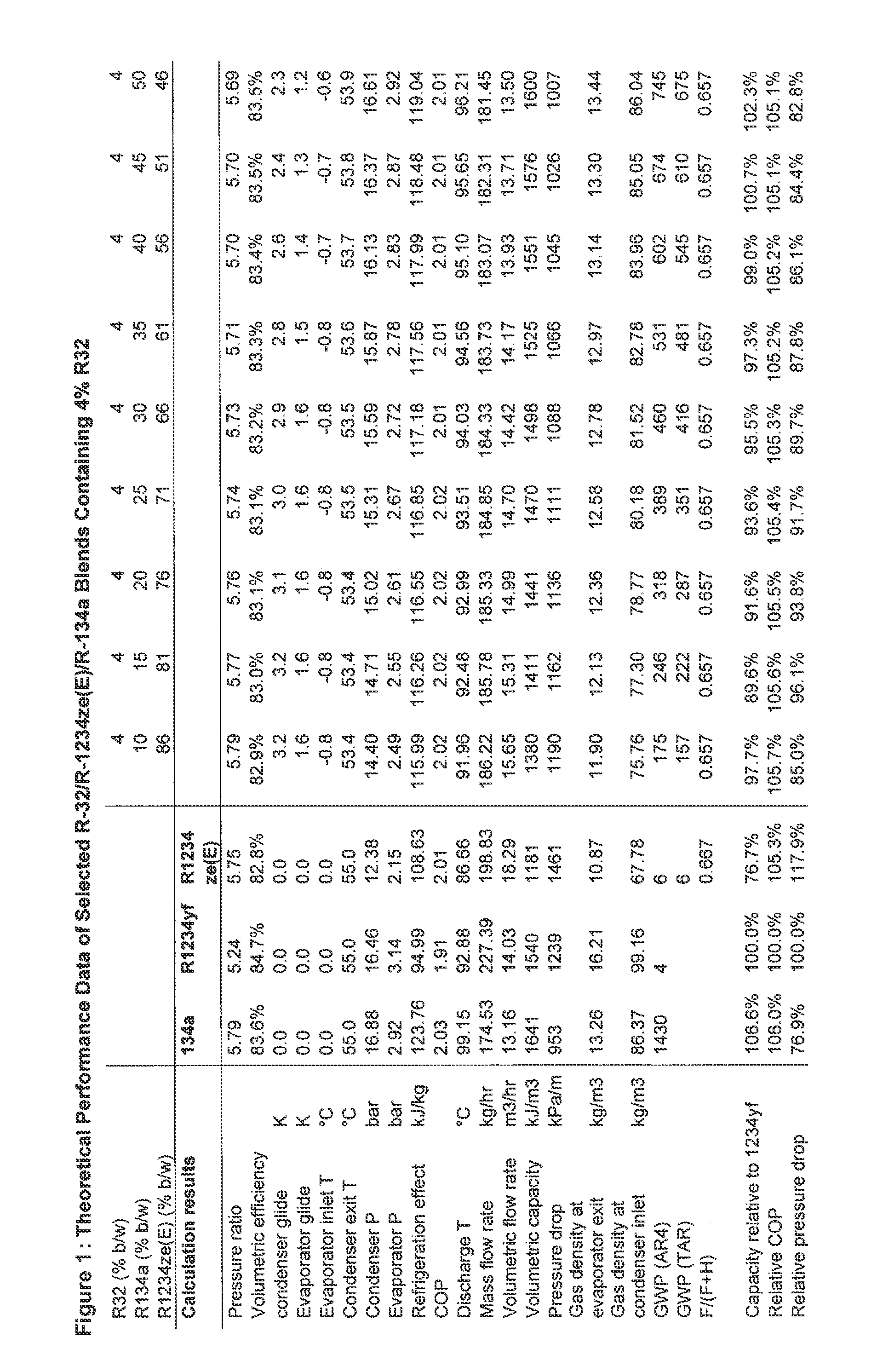
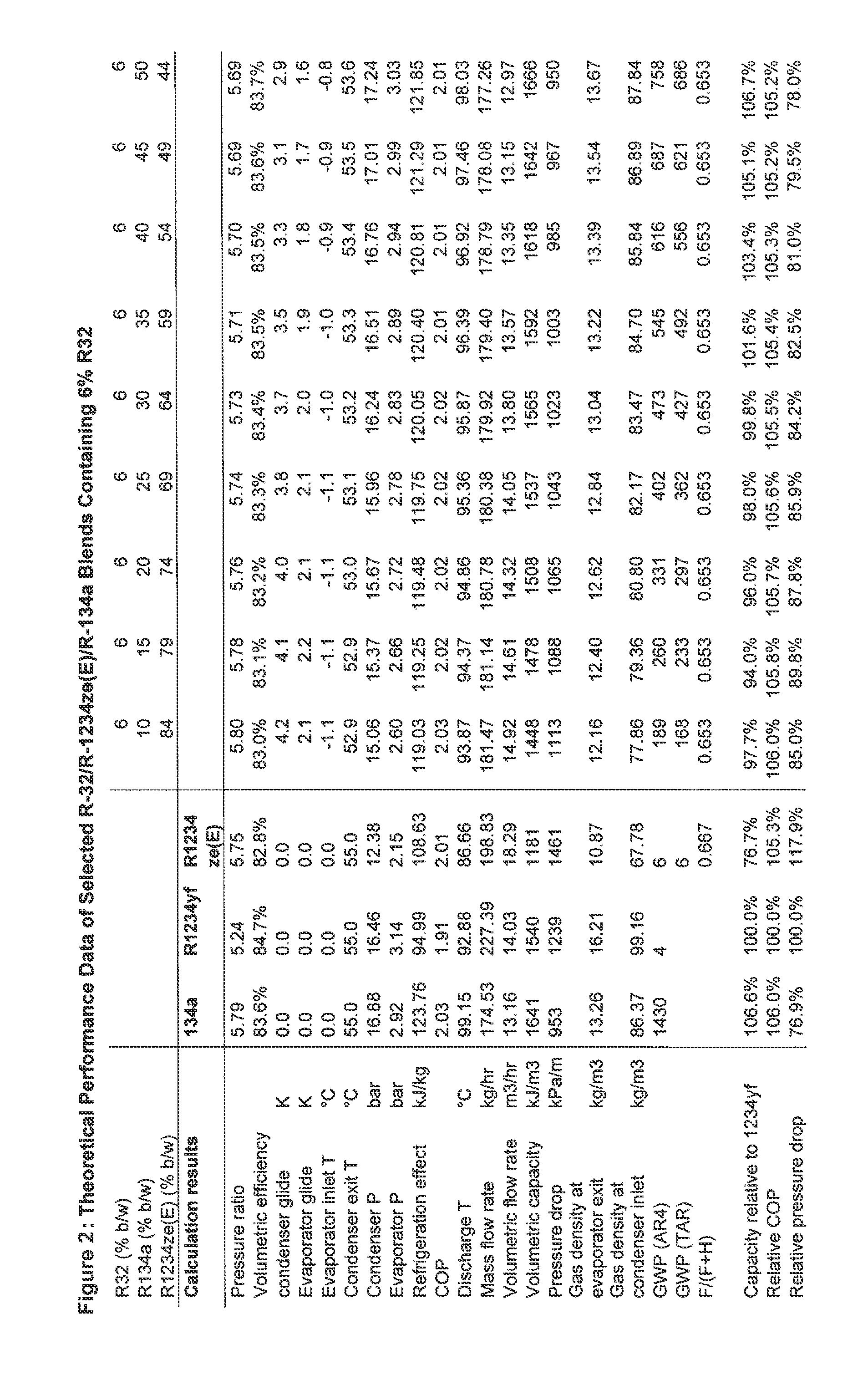
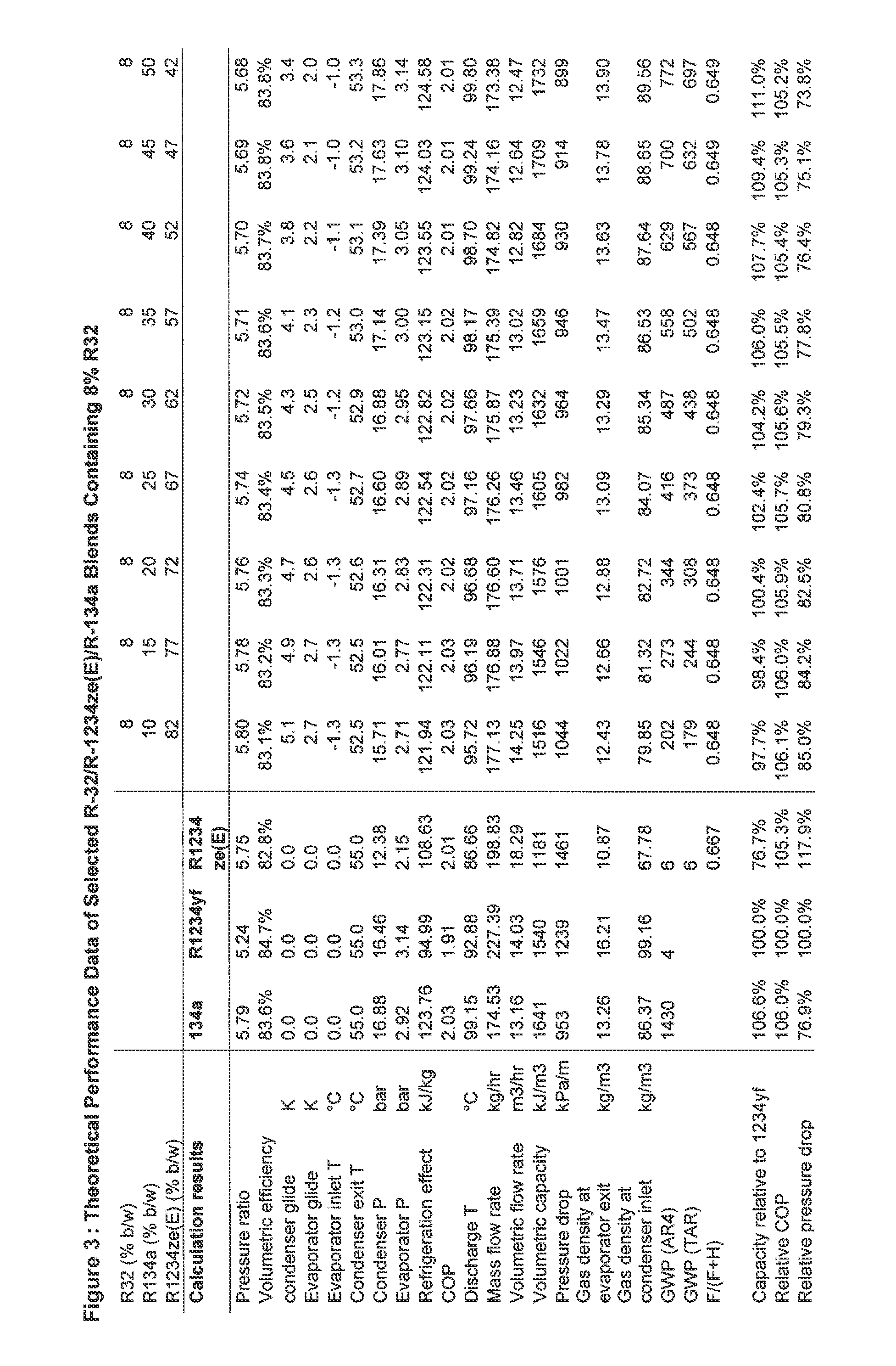
Performance of a R-32 / R-134a / R-1234ze Blend

[0106]An instrumented laboratory chiller was used to evaluate the performance of a ternary blend of R-32 / R-134a / R-1234ze(E) (7% / 46% / 47% weight basis) over a range of evaporating and condensing temperatures. The chiller used a fixed displacement reciprocating compressor with polyolester (POE) lubricant and cooled glycol in a counter-current flow heat exchanger against evaporating refrigerant. The refrigerant was condensed in a counter-current flow heat exchanger using cooling water. The comparative tests were run at fixed compressor displacement and the flowrates of heat transfer fluids were controlled to maintain a constant and equal bubblepoint of refrigerant in the condenser, and a constant evaporator inlet temperature of refrigerant. The performance was evaluated at condenser bubblepoint temperatures of 30° C. and 40° C. and over a range of evaporator inlet temperatures from −35° C. to +5° C.

[0107]Data are reproduced below for the measur...


PUM

PropertyMeasurementUnit
temperature glideaaaaaaaaaa
discharge temperatureaaaaaaaaaa
GWPaaaaaaaaaa

Abstract

The invention provides a heat transfer composition comprising R-1234ze(E), R-32 and 1,1,1,2-tetrafluoroethane (R-134a).

Description

RELATED APPLICATIONS[0001]The present application is a continuation-in-part of U.S. application Ser. No. 13 / 005,373, filed on Jan. 12, 2011, which is a continuation-in-part of U.S. application Ser. No. 12 / 287,880 filed on Oct. 14, 2008, now U.S. Pat. No. 7,914,696, which claims priority to Great Britain Patent Application No. 0719989.6, filed Oct. 12, 2007 and Great Britain Patent Application Number 0814060.0, filed Aug. 1, 2008. U.S. application Ser. No. 13 / 005,373 also claims priority to Great Britain Application No. 1002625.0, filed on Feb. 16, 2010, International Application No. PCT / GB2009 / 002803, filed Dec. 2, 2009, International Application No. PCT / GB2009 / 002805 filed Dec. 2, 2009, International Application No. PCT / GB2009 / 002809, filed Dec. 2, 2009, and International Application No. PCT / GB2010 / 000774, filed 16 Apr. 2010. The present application is also a continuation-in-part of U.S. application Ser. No. 13 / 005,391, which is a continuation-in-part of U.S. application Ser. No. 1...

Claims


Application Information

Patent Timeline
Patent Type & Authority Patents(United States)
IPC IPC(8): C09K5/04
CPCG06Q99/00C09K5/044Y10T29/49718
Inventor LOW, ROBERT E.
Owner MEXICHEM AMANCO HLDG DE C V
Why Eureka
Try Eureka