
Integrated external combustion cam engine-generator

a technology of engine generator and cam engine, which is applied in the direction of machines/engines, mechanical energy handling, mechanical equipment, etc., can solve the problems of not being able to disclose a piston engine with a rotating block, the technique is not acceptable, and the allocation of fuel storage and batteries is small

Inactive Publication Date: 2012-12-18
THE UNITED STATES OF AMERICA AS REPRESENTED BY THE SECRETARY OF THE NAVY
View PDF21 Cites 10 Cited by
  • Summary
  • Abstract
  • Description
  • Claims
  • Application Information

AI Technical Summary

Benefits of technology

[0017]Accordingly it is a primary object and general purpose of the present invention to provide a lighter, more compact engine and generator combination for use in UUVs.
[0021]Standard diesel-electric powerplants have separately housed engine and generator devices operationally connected on a common shaft, whereas the present invention combines the thermal engine portion and permanent magnet generator portion into a single integrated system. This system reduces size and weight and enables smaller and lighter engine-generator systems for UUV applications.
[0022]The rotating block engine design used in the present invention enables integration of the generator with the engine. Also, the multi-lobe cam enables balance of axial forces resulting in reduced axial vibration.

Problems solved by technology

This technique has not yet been accepted in UUVs since the diesel engine and generator occupy a large amount of space and weight; thereby, leaving little allocation for fuel storage and batteries.
This technique is also not acceptable due in part to acoustic signature considerations.
Pinkerton does not disclose a piston engine with a rotating block.

Method used


Image

  • Integrated external combustion cam engine-generator
  • Integrated external combustion cam engine-generator
  • Integrated external combustion cam engine-generator

Examples


Embodiment Construction

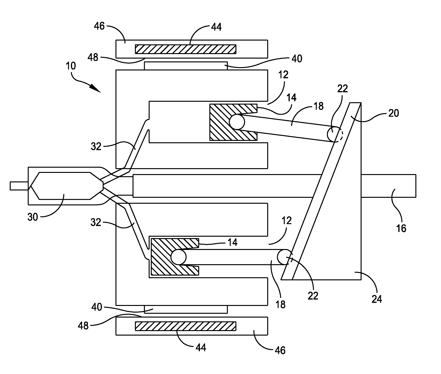
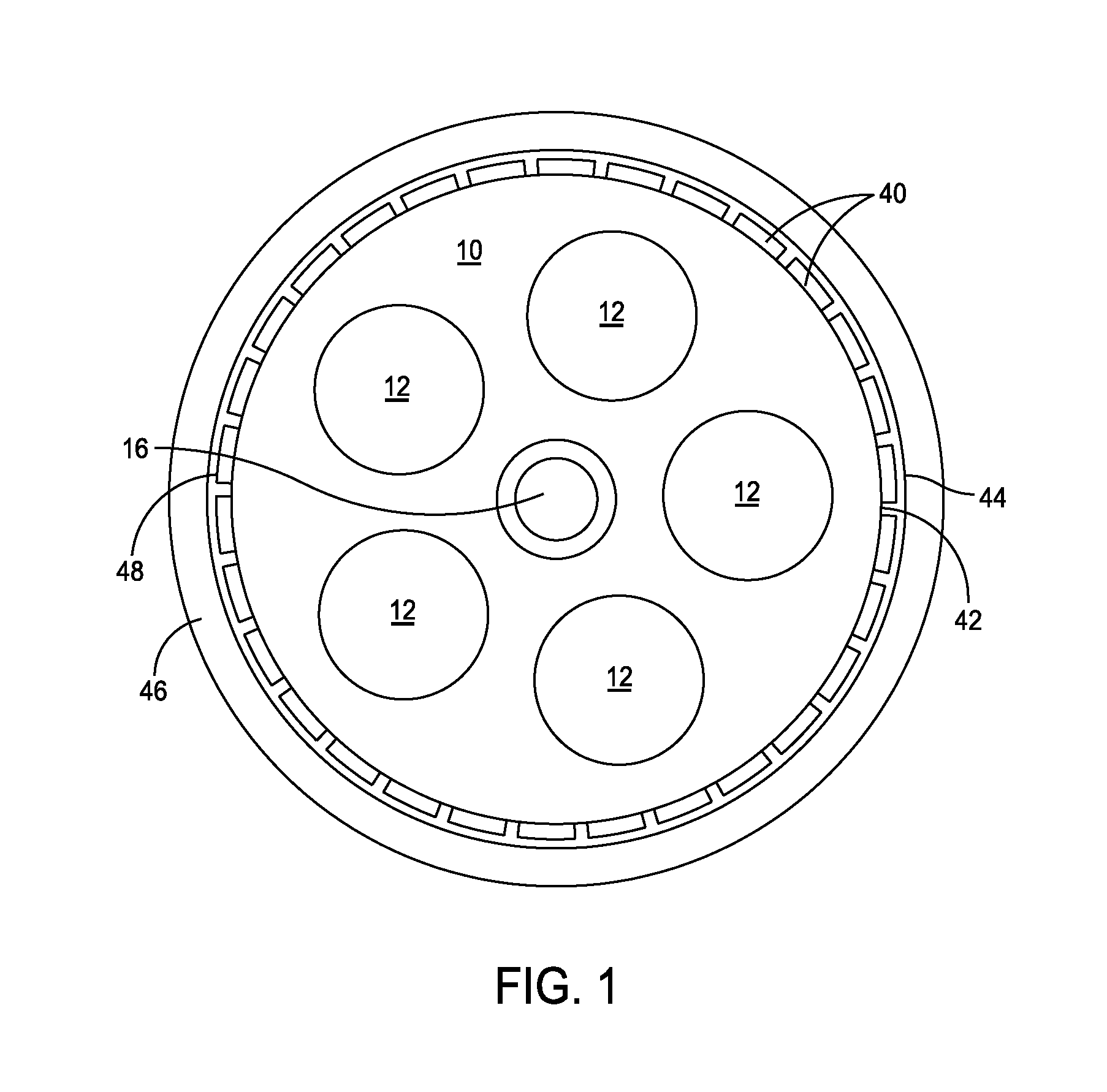
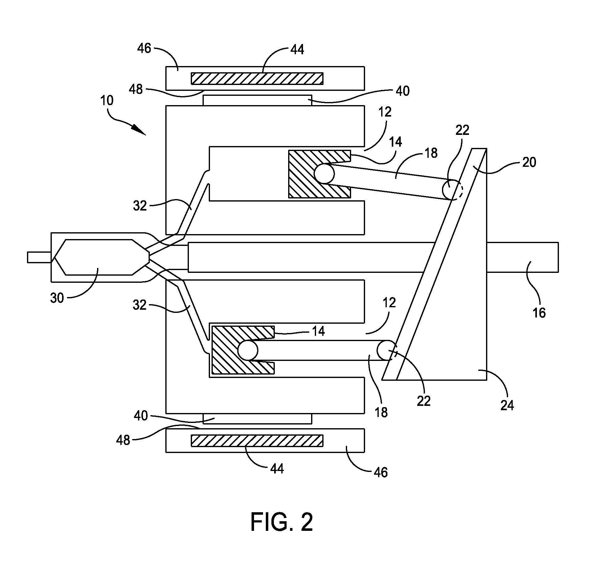
[0027]FIG. 1 and FIG. 2 illustrate a preferred embodiment of a rotating block external combustion cam piston engine. According to the present invention, the engine block rotates about a stationary shaft. The rotating engine block has permanent magnets that are fixedly-attached (either surface-mounted or embedded) to the outer cylindrical surface of the engine block. These magnets rotate within a fixed stator coil, forming the rotating component of the alternator or generator.

[0028]In the figures, the rotating engine block 10 is configured with a number of cylinders 12 in which pistons 14 translate in rectilinear motion while rotating with the engine block about a shaft 16. In the preferred embodiment, five cylinders are shown although this number can vary as needed.

[0029]The pistons 14 are attached by connecting rods 18 to a cam-follower wobble plate 20 and a bearing assembly 22. The stationary shaft 16 and a swash plate 24 are fixed together and remove the rotating moment of the ro...


PUM


Abstract

An integrated engine and generator is provided and includes a stationary non-rotating shaft. An engine block is provided that is capable of rotation about the shaft. The engine block comprises a plurality of cylinders with each cylinder including a piston translating in rectilinear motion while rotating about the shaft. A stationary generator housing and stator surrounds the block and has stator windings wound into the housing. Magnets are affixed to an outer surface of the block to rotate with the block, with the magnets separated from the housing by an air gap. The stator windings are electrically configured to match pole pairs of the magnets in order to generate electrical current upon block rotation.

Description

STATEMENT OF GOVERNMENT INTEREST[0001]The invention described herein may be manufactured and used by or for the Government of the United States of America for governmental purposes without the payment of any royalties thereon or therefor.CROSS REFERENCE TO OTHER PATENT APPLICATIONS[0002]None.BACKGROUND OF THE INVENTION[0003]1. Field of the Invention[0004]The present invention is directed generally to a compact engine-generator (or alternator) combination, and specifically to a more compact engine-generator for use with unmanned submersibles (hereinafter called Unmanned Undersea Vehicles or UUVs).[0005]2. Description of the Prior Art[0006]An Undermanned Undersea Vehicle (UUV), which operates independent of air, must use thermal engines with air-independent fuels, or use electric power with energy delivered via primary batteries, secondary batteries, fuel cells, etc. The range of the UUVs can be significantly increased if an air breathing engine is used to recharge the batteries. This...

Claims


Application Information

Patent Timeline
IPC IPC(8): F02B53/04H02K21/10H02K21/14
CPCH02K7/1815F01B3/0032F02B75/26F02B63/042H02K21/14
Inventor DUNN, PAUL M.EGAN, CHRISTOPHER J.
Owner THE UNITED STATES OF AMERICA AS REPRESENTED BY THE SECRETARY OF THE NAVY
Learn More