Method to achieve constant slew rate (over process corners) for an output buffer

a buffer and output technology, applied in the field of output buffers, can solve the problems of additional calibration circuitry, additional cost, area and labor penalty, etc., and achieve the effect of cost-effective implementation

Active Publication Date: 2012-12-18
AMBARELLA INT LP
View PDF2 Cites 10 Cited by
  • Summary
  • Abstract
  • Description
  • Claims
  • Application Information

AI Technical Summary

Benefits of technology

[0006]The objects, features and advantages of the present invention include providing a method to achieve constant slew rate (over process corners) for an output buffer that may (i) resolve slew rate variation issues, (ii) compensate for capacitor variation, (iii) implement an automatic calibration loop, (iv) be implemented in applications where a current is integrated across a capacitor, (v) be implemented without post-production tuning and / or tuning capacitors, and / or (vi) be cost effective to implement.

Problems solved by technology

Tuning resistors result in an area and labor penalty, as well as additional calibration circuitry, which add to the overall cost.

Method used


Image

  • Method to achieve constant slew rate (over process corners) for an output buffer
  • Method to achieve constant slew rate (over process corners) for an output buffer
  • Method to achieve constant slew rate (over process corners) for an output buffer

Examples


Embodiment Construction

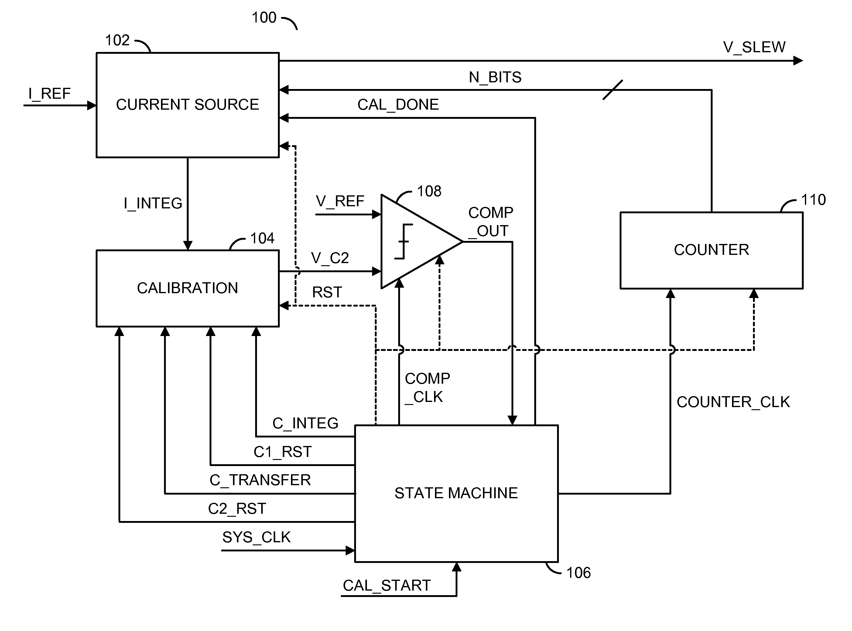
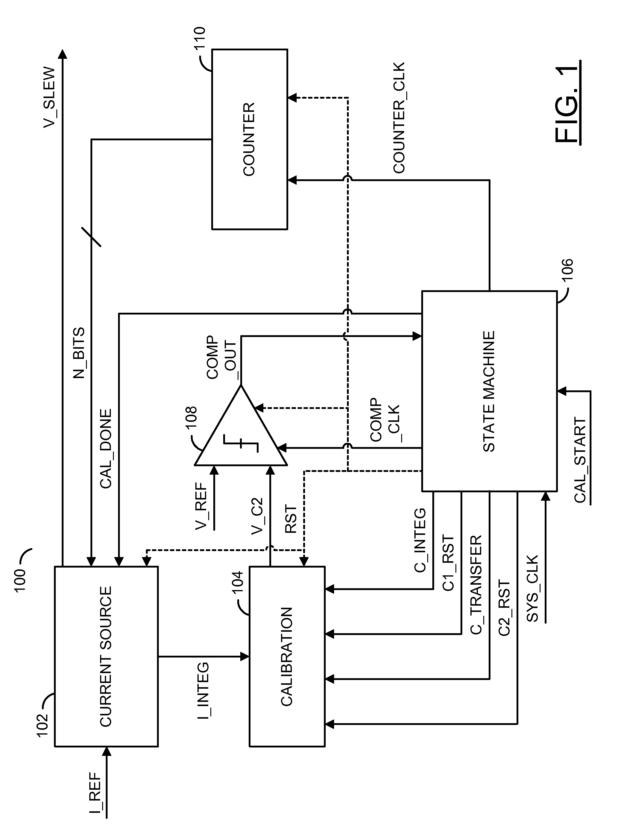
[0014]Referring to FIG. 1, a block diagram of a system 100 is shown in accordance with a preferred embodiment of the present invention. The circuit 100 generally comprises a block (or circuit) 102, a block (or circuit) 104, a block (or circuit) 106, a block (or circuit) 108 and a block (or circuit) 110. The circuit 102 may be implemented as a current source circuit. The circuit 104 may be implemented as a calibration circuit. The circuit 106 may be implemented as a state machine. The circuit 108 may be implemented as a comparator. The circuit 110 may be implemented as a counter circuit. In one example, the circuit 110 may be implemented as an up counter. In another example, the circuit 110 may be implemented as a down counter.

[0015]The circuit 102 may receive a signal (e.g., I_REF), a signal (e.g., N_BITS) and a signal (e.g., CAL_DONE). The circuit 102 may generate a signal (e.g., I_INTEG) and a signal (e.g., V_SLEW). The circuit 104 may receive the signal I_INTEG, a signal (e.g., C...


PUM


Abstract

An apparatus comprising a first circuit, a state machine, a compare circuit and a calibration circuit. The first circuit may be configured to generate a slew rate control signal and a calibration signal in response to (i) a plurality of control bits and (ii) an operation signal. The state machine may be configured to generate the operation signal and a plurality of intermediate control signals in response to (i) a compare signal and (ii) clock signal. The compare circuit may be configured to generate the compare signal in response to (i) a reference voltage and (ii) a capacitance signal. The calibration circuit may be configured to generate the capacitance signal in response to (i) the calibration signal and (ii) the plurality of intermediate control signals.

Description

FIELD OF THE INVENTION[0001]The present invention relates to output buffers generally and, more particularly, to a method and / or apparatus to implement a constant slew rate (over process corners) for an output buffer.BACKGROUND OF THE INVENTION[0002]Conventional output buffers sometimes solve slew rate variation issues by implementing “tuning” capacitors with switchable capacitor banks. The tuning capacitors allow post production tuning. Tuning resistors result in an area and labor penalty, as well as additional calibration circuitry, which add to the overall cost.[0003]Conventional tunable capacitors can be implemented with a bank of switchable capacitors. Depending on the process corners, a certain number of capacitors are switched in or out. Calibration circuitry determines the capacitor variation from the nominal value. In conventional approaches, the switchable capacitor banks need to be implemented as part of the output buffer.[0004]It would be desirable to implement a method ...

Claims


Application Information

Patent Timeline
IPC IPC(8): H03K5/12
CPCH03K19/00384
Inventor MUTHALI, HARISH S.ZHU, XIAOJUN
Owner AMBARELLA INT LP
Why Eureka
Try Eureka