Coil-integrated switching power supply module

a technology of switching power supply module and coil, which is applied in the incorporation of printed electric components, transformer/inductance cooling, printed circuit aspects, etc., can solve the problems of increasing the thickness of the substrate in association with the increase in the number, affecting the performance of components mounted near the coil conductor pattern, and increasing the manufacturing cost of the substrate. , to achieve the effect of low thermal resistan

Active Publication Date: 2012-12-18
MURATA MFG CO LTD
View PDF17 Cites 28 Cited by
  • Summary
  • Abstract
  • Description
  • Claims
  • Application Information

AI Technical Summary

Benefits of technology

[0017]The thermal diffusion conductor pattern or the expansion coil conductor pattern located on the inner layer of the multilayer substrate has a low thermal resistance. Accordingly, the heat radiated from the spiral coil conductor patterns is efficiently diffused in all directions with the thermal diffusion conductor pattern or the expansion coil conductor pattern located on the inner layer of the multilayer substrate. Consequently, the areas where the coil conductor patterns are provided in the multilayer substrate are prevented from being at high temperature intensively to keep the temperature of the entire coil-integrated switching power supply module at a low value.
[0018]In addition, the heat of the thermal diffusion conductor pattern or the expansion coil conductor pattern is efficiently radiated outside through the through holes and the thermal coupling member.

Problems solved by technology

However, the increase in the number of layers of the substrate causes a problem in that the manufacturing cost of the substrate is greatly increased.
In addition, there is a problem in that the thickness of the substrate is also increased in association with the increase in the number of layers to increase the thickness of the product.
In addition, the components mounted near the coil conductor patterns are also adversely affected.
When it is not possible to mount a fan for cooling the coil-integrated switching power supply module or a case in which the coil-integrated switching power supply module is housed or when the environmental temperature is high, the problem of the heat radiation gets worse.

Method used


Image

  • Coil-integrated switching power supply module
  • Coil-integrated switching power supply module
  • Coil-integrated switching power supply module

Examples


first preferred embodiment

[0035]A coil-integrated switching power supply module according to a first preferred embodiment will now be described with reference to FIGS. 3 to 13.

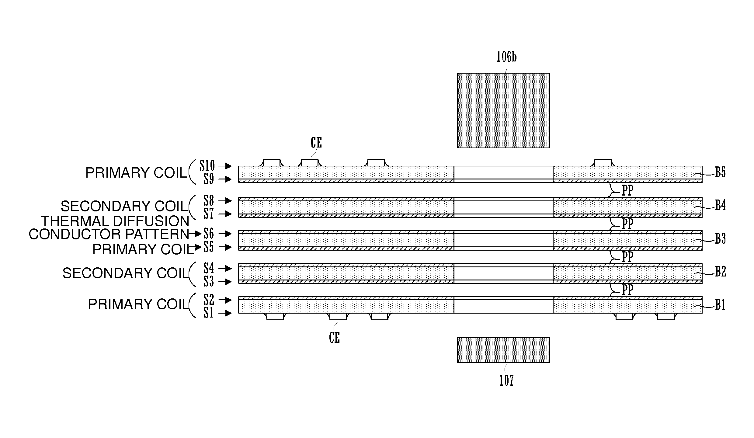
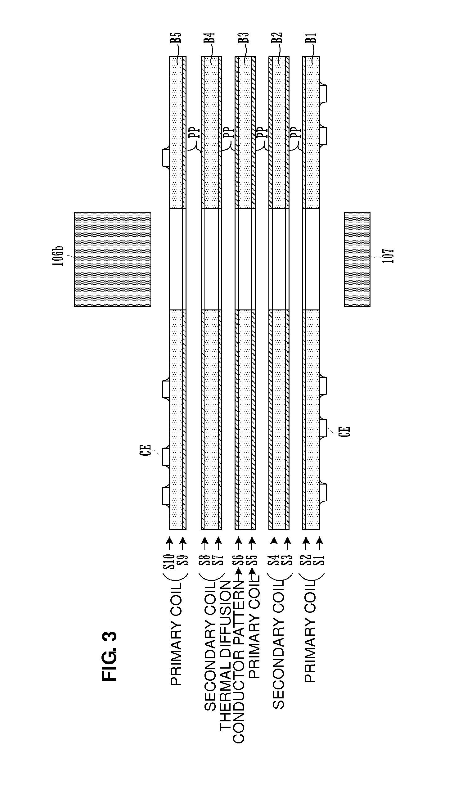
[0036]FIG. 3 is an exploded cross-sectional view of the coil-integrated switching power supply module. A multilayer substrate provided in the coil-integrated switching power supply module includes five double-sided substrates B1, B2, B3, B4, and B5 in this example and prepregs are provided between adjacent double-sided substrates. Since the multilayer substrate includes the five double-sided substrates, the multilayer substrate preferably includes ten layers (layers S1 to S10), for example.

[0037]Among the layers S1 to S10, circuit element mounting electrodes (e.g., lands) are located on the first layer S1 and the tenth layer S10, which are outermost layers, and circuit elements CE are mounted on the electrodes. Since inner via holes are capable of being formed between the first layer and the second layer and between the ninth layer and...

second preferred embodiment

[0066]A coil-integrated switching power supply module according to a second preferred embodiment of the present invention will now be described with reference to FIG. 14. FIG. 14 is a plan view of conductor patterns located on a layer S6 of a multilayer substrate provided in the coil-integrated switching power supply module according to the second preferred embodiment. The layer S6 corresponds to the layer S6 shown in FIG. 9 in the first preferred embodiment but is different from the layer S6 in FIG. 9 in the conductor patterns. The conductor patterns on the other layers are preferably the same as those shown in the first preferred embodiment.

[0067]As shown in FIG. 14, an expansion coil conductor pattern E62 is preferably arranged around the hole H2 on the layer S6. This expansion coil conductor pattern E62 continuously extends in the areas where the coil conductor patterns are located on the other multiple layers and outside the areas where the coil conductor patterns are located o...

third preferred embodiment

[0069]A coil-integrated switching power supply module according to a third preferred embodiment of the present invention will now be described with reference to FIG. 15. FIG. 15 is a cross-sectional view of an electronic device including a coil-integrated switching power supply module 100 according to the third preferred embodiment. Referring to FIG. 15, a multilayer substrate LB preferably is the multilayer substrate of the coil-integrated switching power supply module shown in the first preferred embodiment. This multilayer substrate LB and magnetic cores 106 and 107 define the coil-integrated switching power supply module 100.

[0070]The thermal diffusion conductor pattern E60 is provided in the multilayer substrate LB, as shown in the first preferred embodiment. A mounting electrode for a thermal coupling member HC is located on the upper surface of the multilayer substrate LB and the thermal coupling member HC is mounted on the mounting electrode.

[0071]Conductor through holes PTH...


PUM

PropertyMeasurementUnit
magneticaaaaaaaaaa
thermalaaaaaaaaaa
structureaaaaaaaaaa

Abstract

A coil-integrated switching power supply module that provides an improved heat radiation effect to keep the temperature of the entire coil-integrated switching power supply module to a lower value includes a thermal diffusion conductor pattern arranged around a hole through which a magnetic core extends on a layer. The thermal diffusion conductor pattern continuously extends in areas where coil conductor patterns are located on other layers and outside areas where the coil conductor patterns are located on the other layers. In addition, the thermal diffusion conductor pattern includes slits at portions thereof and does not define a closed loop around the hole through which the magnetic core extends.

Description

BACKGROUND OF THE INVENTION[0001]1. Field of the Invention[0002]The present invention relates to a coil-integrated switching power supply module including a transformer including a power transfer-voltage conversion function between a primary side and a secondary side.[0003]2. Description of the Related Art[0004]Japanese Unexamined Patent Application Publication No. 2000-260639, Japanese Unexamined Patent Application Publication No. 2004-349293, and Japanese Patent Application No. 3196187 each disclose a sheet transformer and an insulated switching power supply using the sheet transformer. The sheet transformer has a structure in which the wiring patterns of a primary wiring and a secondary wiring are formed on multiple substrates, through holes are provided in a multilayer substrate having the multiple substrates stacked therein, and the multilayer substrate is sandwiched with a ferrite core from both sides.[0005]FIG. 1 and FIG. 2 of the present application correspond to FIG. 3 and ...

Claims


Application Information

Patent Timeline
Patent Type & Authority Patents(United States)
IPC IPC(8): H01F5/00
CPCH01F27/22H02M3/28H05K1/165H01F2027/2809H05K1/0207H05K2201/0969H05K1/182H05K2201/086H05K2201/09063H05K2201/093
Inventor MATSUMOTO, TADAHIKO
Owner MURATA MFG CO LTD
Why Eureka
Try Eureka