
Method of fabricating a tunneling magnetoresistive (TMR) reader

a tunneling magnetoresistive and reader technology, applied in the field of magnetic reader and writer fabrication, can solve the problems of data errors in subsequent recordings, deleterious effect on the stability of the read, high bit error rate (ber), etc., and achieve the effect of improving the stability of the reader and improving the overwrite performan

Inactive Publication Date: 2012-12-25
WESTERN DIGITAL TECH INC
View PDF17 Cites 150 Cited by
  • Summary
  • Abstract
  • Description
  • Claims
  • Application Information

AI Technical Summary

Benefits of technology

The patent text describes a method for improving the stability and performance of a tunneling magnetoresistance (TMR) reader. The method involves adding a second thermal annealing process after patterning the TMR stack to improve reader stability, and adding a third thermal annealing process after patterning the writer to improve overwrite performance. The technical effect of this method is to provide a more reliable and efficient TMR reader for use in various applications such as magnetic sensors and data storage devices.

Problems solved by technology

However, if the induced magnetic field is not strong enough, the overwrite or erasing may not be fully effectuated in all magnetic regions, thereby causing data errors in subsequent recordings.
A high value of AASY is undesirable in that it has a deleterious effect on the stability of the read head by causing a high bit error rate (BER) when the data is read back.
As the reader track width decreases, de-magnetic fields from P1 and P2 layers rapidly increases, and the increased de-magnetic field, in turn, causes reader stability degradation by increasing the AASY.
Therefore, it is often neither desirable nor practical to increase the hard bias layer thickness to improve the ASSY.
In addition, an increase in the hard bias thickness causes a significant reduction in the reader amplitude which may not be a good compromise for the improved reader stability.

Method used


Image

  • Method of fabricating a tunneling magnetoresistive (TMR) reader
  • Method of fabricating a tunneling magnetoresistive (TMR) reader
  • Method of fabricating a tunneling magnetoresistive (TMR) reader

Examples


Embodiment Construction

[0021]In the following detailed description, numerous specific details are set forth to provide a full understanding of the present invention. It will be apparent, however, to one ordinarily skilled in the art that the present invention may be practiced without some of these specific details. In other instances, well-known structures and techniques have not been shown in detail to avoid unnecessarily obscuring the present invention.

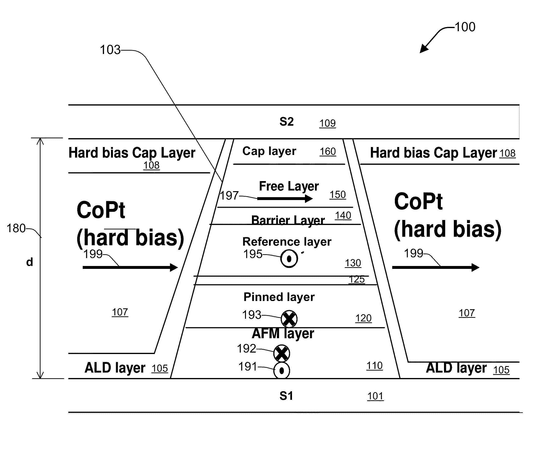
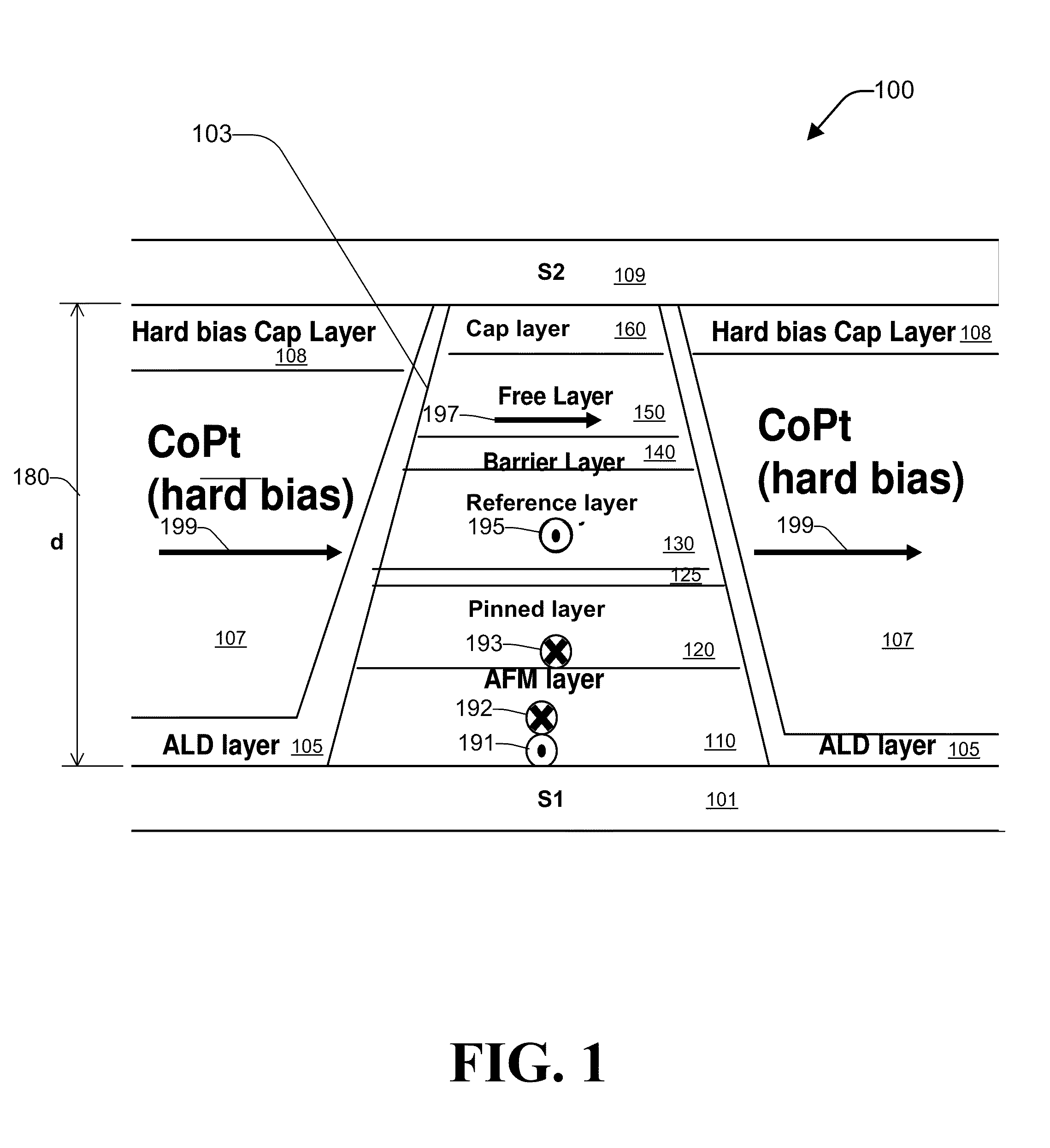
[0022]FIG. 1 is a diagram depicting an exemplary TMR reader 100 according to one aspect of the subject disclosure. The TMR reader 100 includes a patterned TMR stack 103 disposed between a first (bottom) shield layer (S1) 101 and a second (top) shield layer (S2) 109 and having a shield-to-shield distance (d) 180. The TMR reader 100 further includes a hard bias layer 107; an insulating spacer layer 105, typically comprising atomic layer deposition (ALD) alumina (Al2O3), disposed between the first shield layer 101 and the patterned TMR stack 103; and a hard ...


PUM

PropertyMeasurementUnit
temperatureaaaaaaaaaa

Abstract

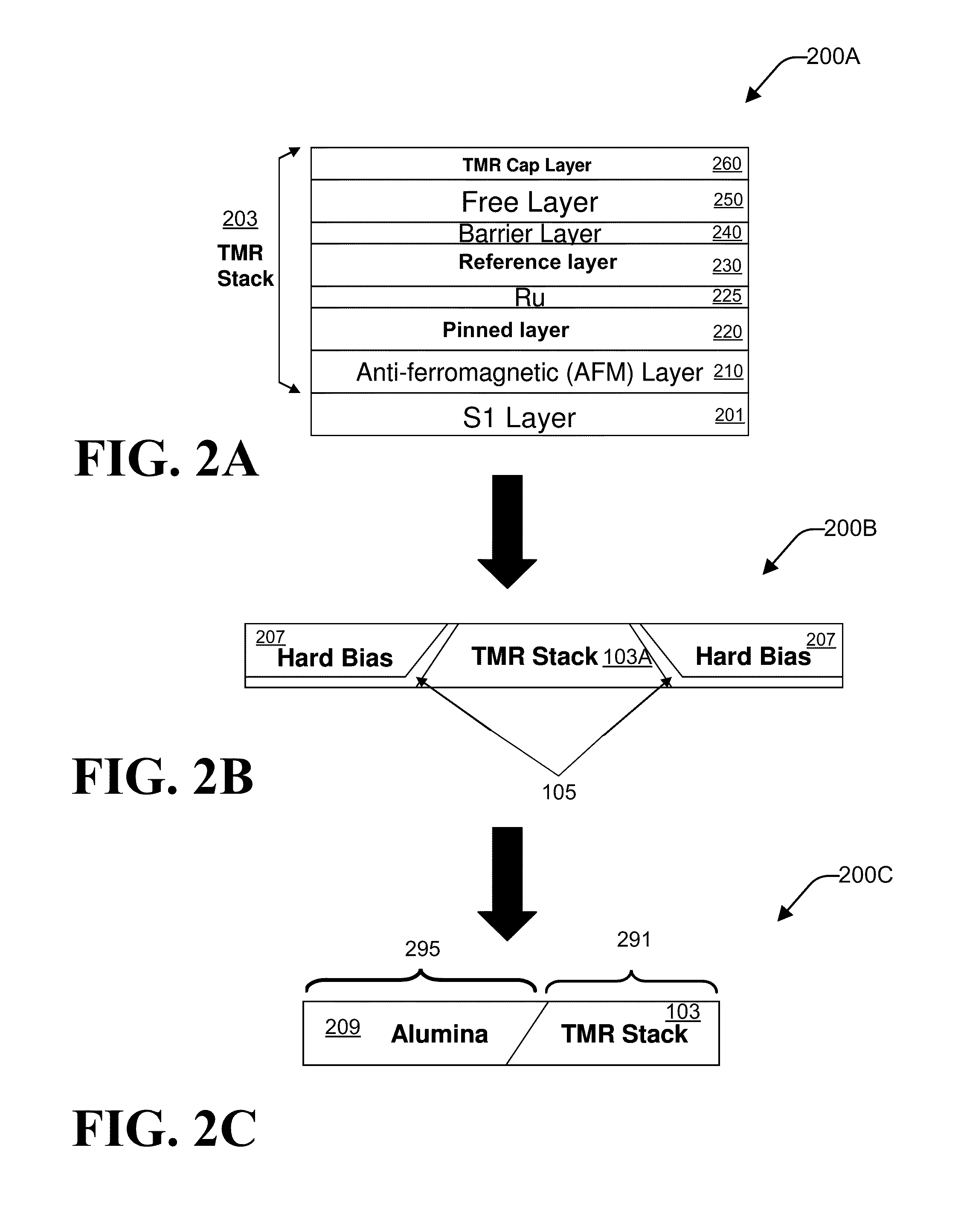
A method of fabricating a tunneling magnetoresistance (TMR) reader is disclosed. A TMR structure comprising at least one ferromagnetic layer and at least one nonmagnetic insulating layer is provided. A first thermal annealing process on the TMR structure is performed. A reader pattern definition process performed on the TMR structure to obtain a patterned TMR reader. A second thermal annealing process is performed on the patterned TMR reader.

Description

FIELD OF THE INVENTION[0001]The present invention generally relates to fabrication of magnetic readers and writers and, in particular, relates to a method to improve reader stability and writer overwrite performance by patterned wafer annealing.BACKGROUND OF THE INVENTION[0002]Perpendicular magnetic recording (PMR), in which the recorded bits are stored in the generally planar recording layer in a generally perpendicular or out-of-plane orientation, is a promising path toward ultra-high recording densities in magnetic recording hard disk drives.[0003]A PMR write head (writer) and a PMR read head (reader) are typically formed as an integrated read / write head on an air-bearing slider. The slider is attached to an actuator arm by a suspension and positioned very close to the disk surface by the suspension. The actuator moves the slider across the disk surface so that the read / write head can access the data tracks. There are typically a stack of disks in the disk drive with a slider-sus...

Claims


Application Information

Patent Timeline
Patent Type & Authority Patents(United States)
IPC IPC(8): G11B5/127H04R31/00
CPCB82Y10/00B82Y25/00G01R33/098G11B5/3163G11B5/3909Y10T29/49048Y10T29/49046Y10T29/49052Y10T29/49044Y10T29/49043Y10T29/49039
Inventor YUAN, LUSHEN, JIAN X.ANDERSON, GEOFFREY W.NG, CHRISTOPHER
Owner WESTERN DIGITAL TECH INC
Learn More