Composite sensor and electronic device

a sensor element and composite technology, applied in the direction of turn-sensitive devices, acceleration measurement using interia forces, instruments, etc., can solve the problems of deteriorating the characteristics, affecting the accuracy of the measurement, and the pressure of the gas surrounding each sensor element is not adjusted to the optimum value, so as to reduce the long-term fluctuation of the characteristics of the vibration-type angular velocity sensor element. , the effect of low cost and small packag

Active Publication Date: 2013-01-01
138 EAST LCD ADVANCEMENTS LTD
View PDF10 Cites 30 Cited by
  • Summary
  • Abstract
  • Description
  • Claims
  • Application Information

AI Technical Summary

Benefits of technology

[0011]An advantage of the invention is to provide a downsized composite sensor that allows sensor elements included therein to well exhibit the characteristics and fluctuation of the characteristics in a long period time to be controlled.
[0012]A composite sensor of the invention includes: a package including a container and a lid; a plurality of spaces that is partitioned by at least the container and the lid, and has different pressures, the plurality of the spaces including a first space sealed at around an atmospheric pressure and a second space sealed at a depressurized state; an acceleration sensor element disposed in the first space; and a vibration type angular velocity sensor element disposed in the second space. In the sensor, the first space has a volume smaller than a volume of the second space. A composite sensor, comprising: a package including a first space having a first pressure and a second space having a second pressure lower than a first pressure; an acceleration sensor element disposed in the first space; and a vibration type angular velocity sensor element disposed in the second space, wherein the first space has a volume smaller than a volume of the second space. The package including a container and a lid and a partitioned member, the first space and the second space is partitioned by the partitioned member.
[0013]The sensor includes the spaces having different pressures in the package, and different kinds of sensor elements are disposed corresponding to the pressures in the respective spaces. As a result, each sensor element well exhibits the characteristics.
[0014]The spaces having different pressures are partitioned by at least the container and the lid that are included in the package. This structure does not need to make a space having a different pressure in the package by putting another package therein. As a result, the composite sensor can be provided with a small package and low costs without needs for an additional lot of members.
[0015]Further, the acceleration sensor element can attain a low Q value since it is disposed in the space having a high pressure while the vibration type angular velocity sensor element can attain a high Q value since it is disposed in the space having a low pressure. As a result, the acceleration sensor element and the vibration type angular velocity sensor element well exhibit the characteristics.
[0016]The pressure inside the space having a low pressure is less affected by a leakage since the space has a large volume. This structure enables a long-term fluctuation of the characteristics of the vibration type angular velocity sensor element to be lessened.

Problems solved by technology

However, the pressure of the gas surrounding each sensor element is not adjusted to the optimum value.
Accordingly, if the whole package is sealed at the atmospheric pressure, the Q value of the angular velocity sensor element is lowered, deteriorating the characteristics.
On the other hand, if the whole package is sealed at a depressurized state, the Q value of the acceleration sensor element is increased, deteriorating the transient response characteristic.
However, the pressure of the gas surrounding each sensor element is also not adjusted to the optimum value.
Further, a plurality of spaces having different pressures provided in one package causes a leak between spaces having different pressures.
It is thus difficult to control the fluctuation of the characteristics in a long period of time.

Method used


Image

  • Composite sensor and electronic device
  • Composite sensor and electronic device
  • Composite sensor and electronic device

Examples


first embodiment

[0040

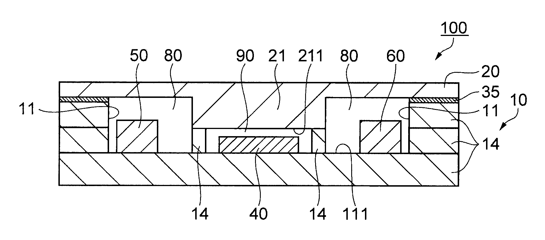
[0041]FIGS. 1A and 1B are schematic views showing a composite sensor 100 according to a first embodiment of the invention. FIG. 1A is a schematic plan view. FIG. 1B is a schematic sectional view taken along the line A-A of FIG. 1A.

[0042]As shown in FIGS. 1A and 1B, the composite sensor 100 includes a package 30 that is composed of a container 10 and a lid 20 and is roughly block-shaped. The package 30 houses an acceleration sensor element 40 and vibration type angular velocity sensor elements 50 and 60.

[0043]The container 10 has a recessed section 11. A step 101 is formed around the periphery of an opening of the recessed section 11. On the other hand, the lid 20 has a protruded section 21. The lid 20 is assembled to the step 101 of the container 10 in a manner such that the protruded section 21 is inside the recessed section 11 of the container 10, and is bonded with a bonding member 35.

[0044]A sealing member (a partitioned member) 70 having a frame shape is disposed between a...

modification 1

[0062

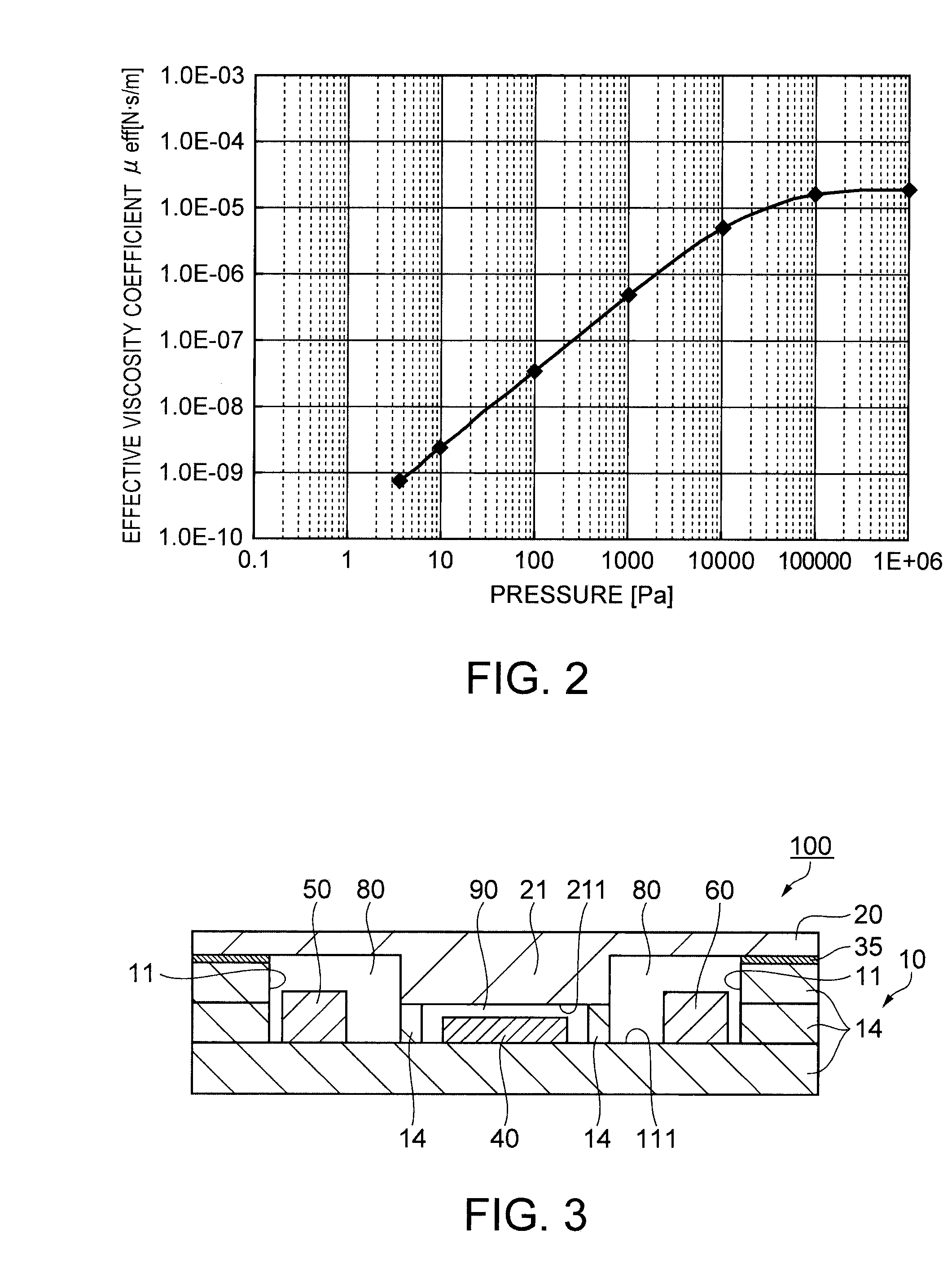
[0063]FIG. 3 is a schematic cross sectional view showing a case in which the container 10 is structured with, for example, layered ceramic plates, which are shown as insulation substrates 14. The through hole 12 and the sealing member 13 are omitted. As shown in FIG. 3, the container 10 has a layered structure composed of the insulation substrates 14. In this case, the sealing member 70 in the first embodiment can be replaced by the insulation substrate 14.

[0064]The shape and the structure of the composite sensor 100 shown in FIG. 3 are roughly the same as those of the first embodiment except that the step 101 supporting the lid 20 is not formed to the container 10. In the modification 1, the lid 20 and the insulation substrate 14 are bonded with the bonding member 35.

[0065]The container 10 and the lid 20 can be made of a number of substrates of an insulation material, such as glass and ceramic, by layering them.

[0066]The modification produces the following effects.

[0067](6) Th...

second embodiment

[0092

[0093]FIG. 5 shows a schematic cross sectional view of a composite sensor 200 according to a second embodiment of the invention. The same numeral is given to the same component of the first embodiment. The differences from the first embodiment are mainly described below. The through hole 12 and the sealing member 13 are omitted.

[0094]The structure of the composite sensor 200 shown in FIG. 5 differs from the composite sensor 100 of the first embodiment in that a recessed section 15 is further provided to the bottom surface 111 of the recessed section 11 of the container 10 instead of providing the sealing member 70.

[0095]The lid 20 has a protruded section 22 formed higher than the protruded section 21 of the first embodiment. When the container 10 and the lid 20 are assembled to be bonded together, an upper surface 221 of the protruded section 22 makes contact with the bottom surface 111 of the recessed section 11 to cover the recessed section 15, forming the space (first space)...


PUM

PropertyMeasurementUnit
thicknessaaaaaaaaaa
massaaaaaaaaaa
pressureaaaaaaaaaa

Abstract

A composite sensor includes: a package including a container and a lid; a plurality of spaces that is partitioned by at least the container and the lid, and has different pressures, the plurality of the spaces including a first space sealed at around an atmospheric pressure and a second space sealed at a depressurized state; an acceleration sensor element disposed in the first space; and a vibration type angular velocity sensor element disposed in the second space. In the sensor, the first space has a volume smaller than a volume of the second space.

Description

BACKGROUND[0001]1. Technical Field[0002]The present invention relates to a composite sensor and electronic device housing sensor elements, such as an acceleration sensor element and a vibration type angular velocity sensor, in the same package.[0003]2. Related Art[0004]Sensor elements used for composite sensors differ in sizes or optimum use environment depending on the kinds thereof. For example, a low Q value is required for an acceleration sensor element detecting a movement of a movable section from a point view of a transient response or a shock resistance. In contrast, a higher Q value is required for a vibration type angular velocity sensor element as compared to the acceleration sensor element. Both sensor elements include movable sections. The Q value is designed by utilizing viscosity of a gas surrounding the sensor element. The pressure surrounding the sensor element, thus, needs to be changed for attaining the designed Q.[0005]Specifically, the acceleration sensor elemen...

Claims


Application Information

Patent Timeline
Patent Type & Authority Patents(United States)
IPC IPC(8): G01P1/02G01C19/56G01C19/5783G01L7/00G01P15/08G01P15/125
CPCG01C19/56G01P1/023B81C1/00293B81B2201/0242B81B2201/0235G01P2015/0814B81B7/02H01L2224/16225
Inventor OSHIO, MASAHIRO
Owner 138 EAST LCD ADVANCEMENTS LTD
Why Eureka
Try Eureka