Coriolis gyro
a gyro and coriolis technology, applied in the field of coriolis gyros, can solve the problems of quadrature compensation, i.e., virtually impossible “balancing-out” of the structure by an actuating element, and many force transmitters (e.g. electrostatic force transmitters) and taps, and achieve the effect of reducing the sensitivity to acceleration and vibration
- Summary
- Abstract
- Description
- Claims
- Application Information
AI Technical Summary
Benefits of technology
Problems solved by technology
Method used
Image
Examples
first embodiment
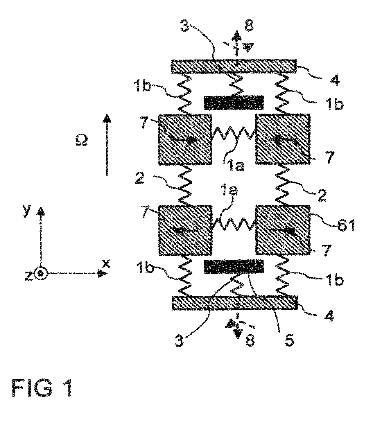
[0028]FIG. 1 is a mechanical schematic diagram of a Coriolis gyro based on a spring and mass system, in a first embodiment, having four first mass elements 61 coupled via first x coupling spring elements 1a and coupling spring elements 2 to one another. The described elements are coupled via second x coupling spring elements 1b, connecting elements 4 and first substrate spring elements 3 to a substrate 5 (shown in FIG. 1 by means of an anchor). Two coupled out-of-phase linear oscillations of the mass elements 61, again out-of-phase with respect to one another, serve as the excitation mode 7. When the Coriolis gyro is rotated about a sensitive axis Ω, a detection mode 8 is excited (represented as two coupled out-of-phase rotary oscillations about a y axis parallel to the sensitive axis Ω and at right angles to the x direction (Lin-Rot)). The x coupling spring elements 1a, 1b are soft in the x direction, and otherwise stiff. The coupling spring elements 2 may be isotropically soft (i....
third embodiment
[0031]FIG. 3 is a schematic diagram of a Coriolis gyro based on a spring and mass system. Four third mass elements 63 are coupled via xy coupling spring elements 23 to one another and to a substrate 5 (illustrated by an anchor 24). Linear oscillations of the mass elements 63 at 45° to the x and y directions are used as the excitation mode 7. In this case, two obliquely opposed third mass elements 63 each move towards one another when the respective other two opposed third mass elements 63 move away from one another. During rotation of the Coriolis gyro about the sensitive axis Ω (at right angles to the x and y directions and therefore parallel to the z direction), a linear oscillation is excited as the detection mode, and is shifted with respect to the excitation mode (Lin-Lin). In this case, the third mass elements 63, which are adjacent in the x direction, move towards one another in the x direction when third mass elements 63, adjacent in the y direction, are moving away from one...
fourth embodiment
[0032]FIG. 4 is a schematic diagram of a Coriolis gyro based on a spring and mass system. Four fourth mass elements 64 are coupled to one another and to a substrate 5 (in this case illustrated by an anchor 26) via further xy coupling spring elements 25. Linear oscillations of the fourth mass elements 64 in the x direction are used as the excitation mode 7. Two fourth mass elements 64, which are adjacent in the x direction, move towards one another when the other two fourth mass elements 64 are moving away from one another in the x direction. During rotation of the Coriolis gyro about the sensitive axis Ω, which is at right angles to the x and y directions (and therefore parallel to the z direction), linear oscillation is excited as the detection mode, and shifted with respect to the excitation mode (Lin-Lin). In this case, two fourth mass elements 64, adjacent in the y direction, move towards one another when the two other fourth mass elements 64 are moving away from one another. Th...
PUM
 Abstract
Description
Claims
Application Information
 - R&D
- Intellectual Property
- Life Sciences
- Materials
- Tech Scout
- Unparalleled Data Quality
- Higher Quality Content
- 60% Fewer Hallucinations
Browse by: Latest US Patents, China's latest patents, Technical Efficacy Thesaurus, Application Domain, Technology Topic, Popular Technical Reports.
© 2025 PatSnap. All rights reserved.Legal|Privacy policy|Modern Slavery Act Transparency Statement|Sitemap|About US| Contact US: help@patsnap.com


