System and method for injecting fuel to a gaseous fueled engine

a fuel injection system and fuel control technology, applied in the direction of electric control, engine starters, machines/engines, etc., can solve the problems of difficult starting of gaseous fueled engines, difficult to start gaseous fueled engines, and the type of fuel injector may require more expensive electronic driver technology, so as to reduce engine emissions, reduce oil consumption, and reduce undesirable emissions

Inactive Publication Date: 2013-01-08
FORD GLOBAL TECH LLC
View PDF20 Cites 10 Cited by
  • Summary
  • Abstract
  • Description
  • Claims
  • Application Information

AI Technical Summary

Benefits of technology

[0002]Gaseous fueled internal combustion engines are one way to reduce oil consumption and reduce engine emissions. Gaseous fueled engines may provide several advantages over liquid fuels such as gasoline or alcohol. For example, gaseous fuels vaporize well at low temperatures. Further, gaseous fuels may combust more completely because the fuel does not condense in the engine before combustion. Therefore, gaseous fuels may produce fewer undesirable emissions during some conditions.
[0006]Engine cold starting of a gaseous fueled engine can be improved by adjusting start of injection timing (e.g., the crankshaft angle at which a fuel injector is commanded to begin to deliver fuel to an engine during a cylinder cycle) to coincide with a time during which voltage supplied to a fuel injector is at a higher level. By starting fuel injection at a time when voltage applied to a fuel injector is higher, the possibility of the fuel injector operating and injecting fuel can increase. For example, for a single cylinder engine, battery voltage can increase while a starter is engaged during an expansion stroke of a cylinder. During an expansion stroke, the compressed cylinder gases expand to accelerate the crankshaft and lower current drawn by the starter. Therefore, it may be beneficial during some conditions to actuate a gaseous fuel injector during an expansion stroke of a cylinder or at another crankshaft interval when voltage supplied to a fuel injector is higher. In this way, lower cost saturation type fuel injectors may be operated such that gaseous fuel is delivered to the engine even when battery voltage is not as high as is desirable. In the case of a multi-cylinder engine, the gas torques of all cylinders are superimposed to yield a net gas torque. The region of minimum gas torque may yield the fastest crank speed, the lowest starter current, and the highest battery voltage.
[0008]The present description may provide several advantages. Specifically, the approach may improve engine starting and emissions. Further, the method can reduce system cost because a peak and hold circuitry is not required to operate the gaseous fuel injector. Further still, the vehicle power system may not have to be upgraded to operate fuel injectors during cold conditions.

Problems solved by technology

Further, gaseous fuels may combust more completely because the fuel does not condense in the engine before combustion.
However, the present inventors have determined that it may be difficult to start a gaseous fueled engine at low temperatures because fuel injectors resist movement at lower temperatures and because vehicle voltage may drop to a level where it may be difficult to operate the gaseous fuel injector.
In addition, it should be noted that although some types of fuel injectors may produce more fuel injector opening force at lower temperatures (e.g., peak and hold fuel injectors—fuel injectors that are actuated at a higher voltage and held open at a lower voltage), this type of fuel injector may require more expensive electronic driver technology.
Therefore, peak and hold fuel injectors may be less desirable.
However, saturating fuel injectors have not been developed that operate at low minimum operating voltage that may be experienced at low temperatures.

Method used


Image

  • System and method for injecting fuel to a gaseous fueled engine
  • System and method for injecting fuel to a gaseous fueled engine
  • System and method for injecting fuel to a gaseous fueled engine

Examples


Embodiment Construction

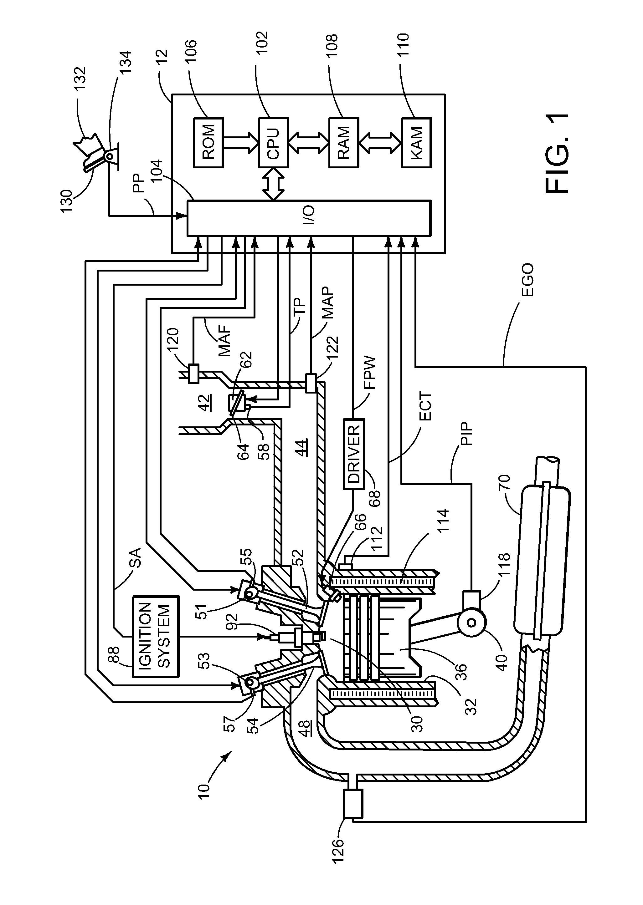
[0019]FIG. 1 shows an exemplary embodiment of a gasoline direct injection engine system generally at 10. Specifically, internal combustion engine 10 comprises a plurality of cylinders, one cylinder of which is shown in FIG. 1. Engine 10 is controlled by electronic engine controller 12. Engine 10 includes combustion chamber 30 and cylinder walls 32 with piston 36 positioned therein and connected to crankshaft 40. Combustion chamber 30 communicates with an intake manifold 44 and an exhaust manifold 48 via respective intake valve 52 and exhaust valve 54. Intake valve 52 is operated by variable position cam 51. Exhaust valve 54 is operated by variable position cam 53. The position of intake cam 51 is sensed by cam sensor 55. The position of exhaust cam 53 is sensed by cam sensor 57.

[0020]Intake manifold 44 communicates with throttle body 62 via throttle plate 64. In one embodiment, an electronically controlled throttle can be used. In one embodiment, the throttle is electronically contr...


PUM


Abstract

A method for controlling injection timing for a gaseous fuel injector is described. In one example, the fuel injector is opened with a saturating fuel injector at a predetermined crankshaft angular position. In one embodiment, the predetermined crankshaft angular position corresponds to at least one crankshaft angular position where battery voltage increases during engine cranking.

Description

TECHNICAL FIELD[0001]The present application relates to the field of automotive fuel control systems and methods.BACKGROUND AND SUMMARY[0002]Gaseous fueled internal combustion engines are one way to reduce oil consumption and reduce engine emissions. Gaseous fueled engines may provide several advantages over liquid fuels such as gasoline or alcohol. For example, gaseous fuels vaporize well at low temperatures. Further, gaseous fuels may combust more completely because the fuel does not condense in the engine before combustion. Therefore, gaseous fuels may produce fewer undesirable emissions during some conditions.[0003]However, the present inventors have determined that it may be difficult to start a gaseous fueled engine at low temperatures because fuel injectors resist movement at lower temperatures and because vehicle voltage may drop to a level where it may be difficult to operate the gaseous fuel injector. In particular, as engine cranking torque increases, the engine speed and...

Claims


Application Information

Patent Timeline
Patent Type & Authority Patents(United States)
IPC IPC(8): F02M51/00
CPCF02D41/0027F02D41/064F02D41/345F02N19/00F02D19/024F02D2041/2051F02N2200/063F02N2250/02Y02T10/44Y02T10/32Y02T10/30Y02T10/40
Inventor PURSIFULL, ROSS DYKSTRA
Owner FORD GLOBAL TECH LLC
Why Eureka
Try Eureka