
System for measuring a physical variable

a technology of physical variables and measurement systems, applied in liquid/fluent solid measurement, instruments, machines/engines, etc., can solve the problems of corrupting the measurement effect, affecting the accuracy of measurement, so as to achieve less magnitude and high amplification

Active Publication Date: 2013-01-15
TECAN TRADING AG
View PDF6 Cites 2 Cited by
  • Summary
  • Abstract
  • Description
  • Claims
  • Application Information

AI Technical Summary

Benefits of technology

[0033]It is the object of the present invention to provide a system for measuring a physical value having multiple measuring sensors, using which the influence of crosstalk between adjacent measuring sensors may be decreased.
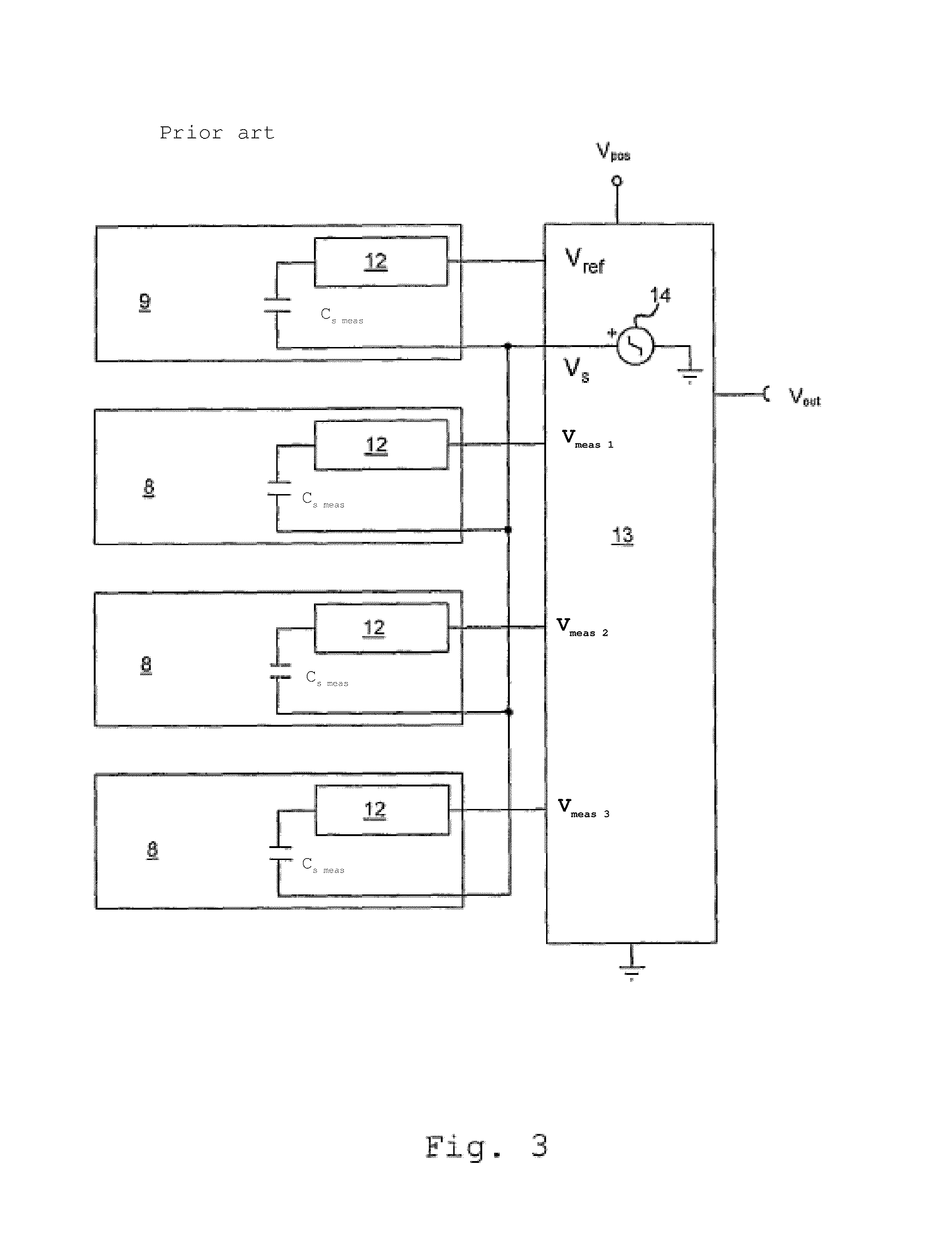
[0036]The inverting input of an inverting measuring signal amplifier represents a virtual ground. The outputs of the measuring sensors, in particular the receiver electrodes of the measuring sensors, are thus virtually grounded. This advantageously has the result that a capacitive crosstalk between adjacent measuring sensor outputs, in particular between adjacent receiver electrodes, may be reduced. In addition, the influence of a parasitic parallel capacitance between a measuring sensor output and / or a receiver electrode and ground is reduced.
[0038]In this way, the output signal of the system according to the invention may advantageously be essentially independent of the operating frequency. This results in a reduced aging and temperature drift. Furthermore, a low-pass behavior of the system is achieved for the upper operating frequency range, so that high-frequency noise may be suppressed.
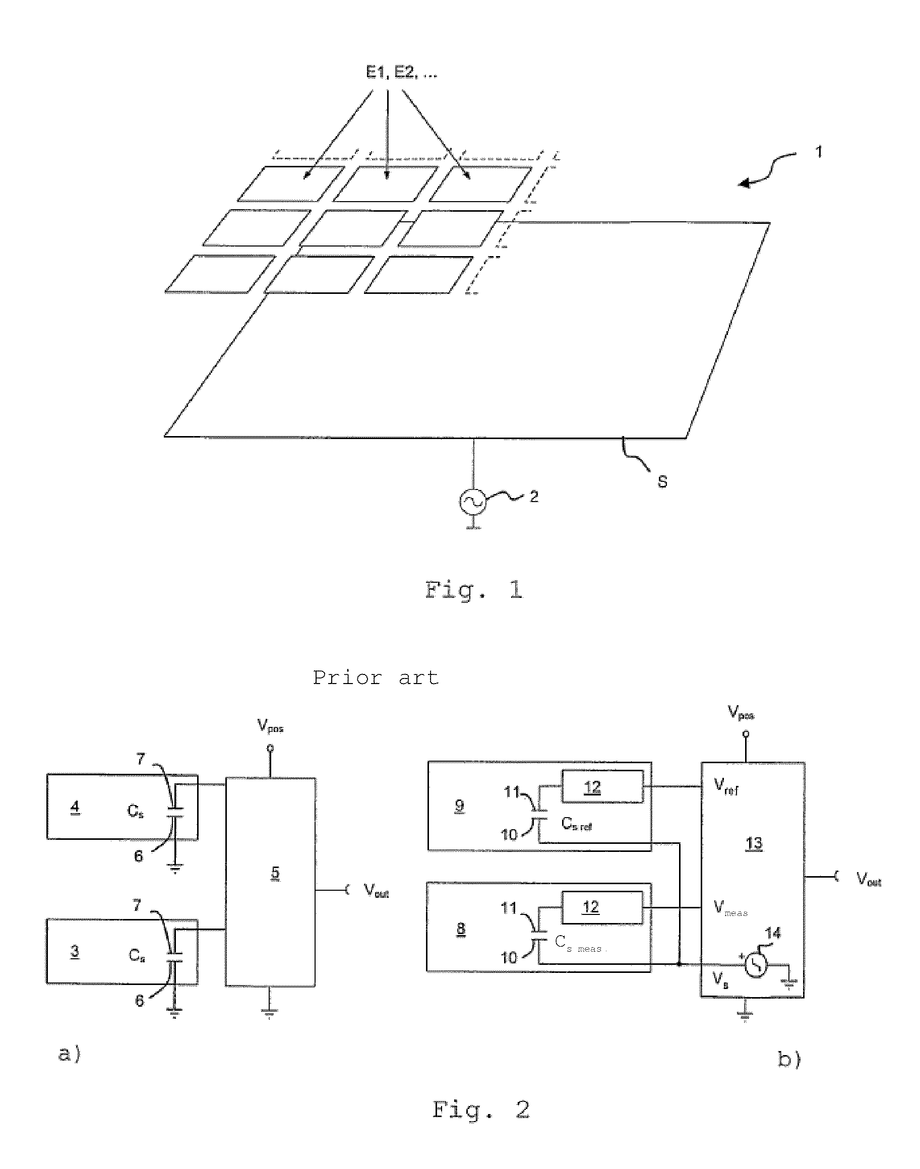
[0040]By subtracting the output signal of the inverting reference signal amplifier from the output signal of the inverting measuring signal amplifier, a signal may be ascertained which corresponds to the change of the sensor capacitance and is of substantially lesser magnitude than the measuring signal or the reference signal. Because of its low amplitude, the differential signal may be provided to a control / analysis unit with a high amplification, without the danger of overload. Furthermore, the differential signal is more sensitive to a change of the sensor capacitance than the measuring signal of the measuring sensor. The danger of crosstalk between the lines which connect the receiving electronics 12 (compare FIG. 2) to the control / analysis unit 13 (compare FIG. 2) is reduced, because the signal amplitudes are less.

Problems solved by technology

In grounded operation of sensors which are situated closely adjacent, a signal voltage typically occurs at the ungrounded electrode which may cause crosstalk by parasitic capacitive coupling to the ungrounded electrode of an adjacent sensor.
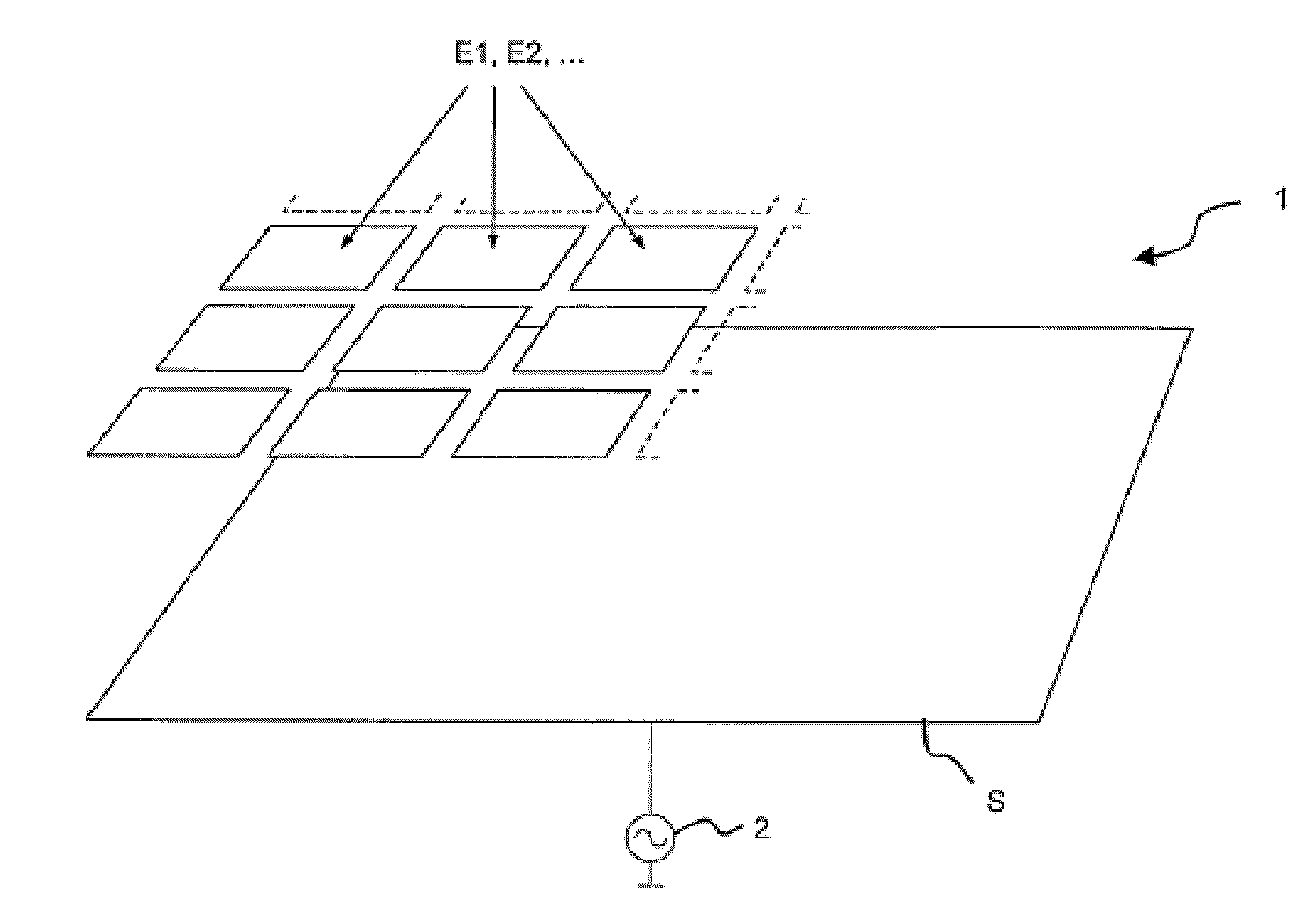
In sensor systems having multiple capacitive sensors, crosstalk capacitances frequently occur, which may corrupt the measuring results. FIG. 4 schematically shows a sensor system, which is operated floating, having multiple capacitive sensors as a concentrated capacitance model.
The further capacitances shown in the capacitance model are parasitic and have a corrupting effect on the measurement results.
Crosstalk capacitances between receiver electrodes situated at a large spatial distance are typically small in comparison to the remaining capacitances of the model and therefore may often be neglected.
Each signal received by a receiver electrode is overlaid via the particular crosstalk capacitances with components of signals received by the adjacent receiver electrodes, which results in a corruption of the amplitude of the output signals and thus in a spatial resolution loss.
However, this requires good stabilization of the operating frequency.
The parallel capacitance Cp1 thus has an unfavorable effect on the ascertainment of the sensor capacitance change.

Method used


Image

  • System for measuring a physical variable
  • System for measuring a physical variable
  • System for measuring a physical variable

Examples


Embodiment Construction

[0033]It is the object of the present invention to provide a system for measuring a physical value having multiple measuring sensors, using which the influence of crosstalk between adjacent measuring sensors may be decreased.

[0034]This object is achieved by a system having the features of claim 1.

[0035]The system according to the invention is characterized in that an inverting measuring signal amplifier is connected downstream from each measuring sensor, one output of a measuring sensor being connected to one negative input of the inverting measuring signal amplifier connected downstream from the measuring sensor in each case. The multiple measuring sensors are preferably capacitive sensors, which are preferably formed by one transmitter electrode and multiple receiver electrodes, the receiver electrodes being situated spaced apart from the transmitter electrode. Alternatively, the transmitter electrode and the receiver electrodes may also be exchanged, so that the sensors are forme...


PUM


Abstract

The invention relates to a system for measuring a physical variable using a plurality of measuring sensors (20). Said system is characterized in that an inverting measuring signal amplifier (17; 17.1, 17.2) is connected downstream of every measuring sensor (20), one output of a sensor (20) each being connected to an inverting input of the measuring signal amplifier (17; 17.1, 17.2) connected downstream of the measuring sensor (20).

Description

NOTICE OF RELATED APPLICATIONS[0001]This application claims the priority of Swiss Patent Application 1957 / 06, which was filed on 1 Dec. 2006 and the content of whose disclosure is hereby incorporated by reference in its entirety.TECHNICAL AREA[0002]The invention relates to a system for measuring a physical value according to the preamble of claim 1.PRIOR ART[0003]Capacitive sensors are frequently used for measuring physical values, such as pressure, fill level, volume, or the relative dielectric index, which operate on the basis of the change of the capacitance of a single capacitor or an entire capacitor system through the physical value to be measured. The physical value to be measured is concluded by measuring the capacitance of the sensor. Capacitive sensors are used either individually or in systems of multiple spatially closely adjacent sensors. Capacitive individual sensors are used, for example, for pressure, acceleration, and position measurements. Capacitive systems and / or...

Claims


Application Information

Patent Timeline
Patent Type & Authority Patents(United States)
IPC IPC(8): G01F23/26
CPCG01D3/036G01D5/24G01L1/144G01L1/146G06F3/044G01R27/2605G06F2203/04107
Inventor KAMM, LARSHINN, WERNERBAUMANN, ROMAN
Owner TECAN TRADING AG
Learn More