
Quick adjustment mechanism for head or helmet mounted displays

a quick adjustment and display technology, applied in the field can solve the problems of difficult adjustment and time-consuming of head/helmet mounted displays (hmds), the '783 patent system is relatively complicated and time-consuming, and the interface is not intuitively located or designed for easy operation

Active Publication Date: 2013-01-15
ROCKWELL COLLINS INC
View PDF10 Cites 21 Cited by
  • Summary
  • Abstract
  • Description
  • Claims
  • Application Information

AI Technical Summary

Benefits of technology

The present invention is a quick adjustment assembly for a head-mounted display for aviators and trainees. It allows for easy adjustment of the display to different users and head sizes with minimal training time and cost. The assembly includes an adjustment plate and a pressure plate friction pad for selectable positioning of the display. The technical effects of this invention include intuitive adjustment interfaces, low part count, and simple part design for high production manufacturing. It also has repeatedly been demonstrated to be fully adjusted in 15 seconds and less by new users.

Problems solved by technology

Head / Helmet Mounted Displays (HMDs) are often difficult and time consuming to adjust and sometimes require a technician to perform the adjustment for the user.
The '783 patent system is relatively complicated and time-consuming.
These interfaces are not intuitively located or designed for easy operation.
For example, an inverting arm that attaches to a display slide assembly appears to be flimsy and unstable.
Some of the parts also seem to be very complicated and difficult to manufacture.
Interfaces are not intuitive and difficult to find blindly.
The IPD knob adjusts both eyes at once which provides a deficiency because people's faces / eyes are not perfectly symmetrical about the centerline of the head.
The NVIS device does not appear to provide for very quick adjustment.
Furthermore, it is not intuitive as to where the IPD knobs are positioned.

Method used


Image

  • Quick adjustment mechanism for head or helmet mounted displays
  • Quick adjustment mechanism for head or helmet mounted displays
  • Quick adjustment mechanism for head or helmet mounted displays

Examples


Embodiment Construction

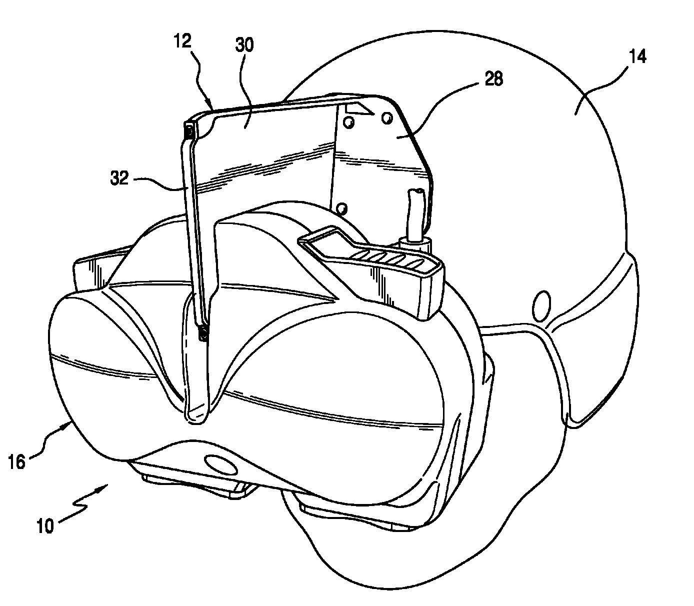
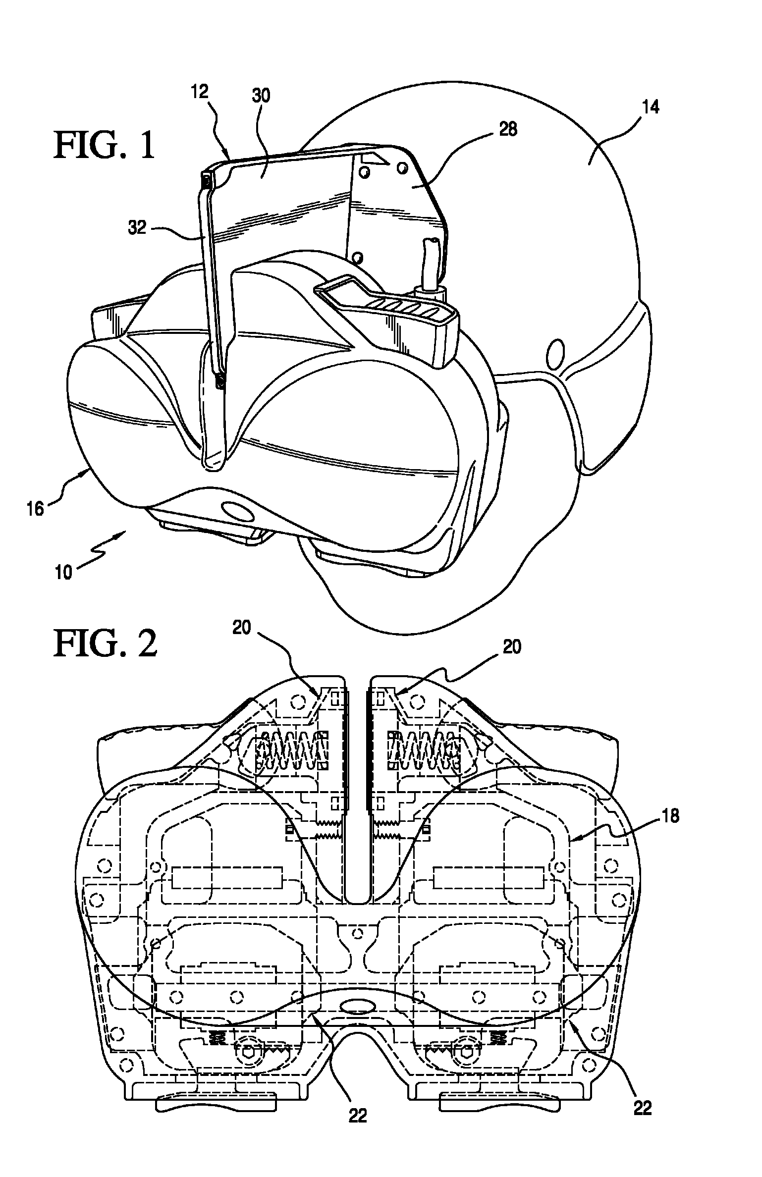
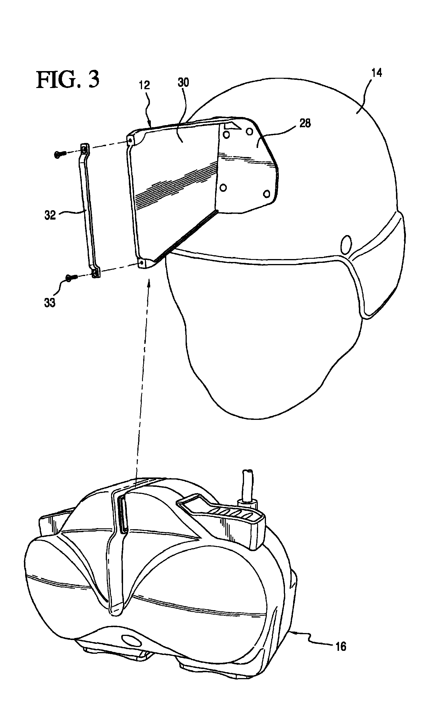
[0032]Referring now to the drawings and the characters of reference marked thereon, FIG. 1 illustrates a preferred embodiment of the quick adjustment assembly of the present invention, designated generally as 10. The quick adjustment assembly 10 includes an adjustment plate assembly, designated generally as 12, which is securely attachable to the head of a user via a helmet 14 or headgear. An eye relief assembly 16 is mountable on the adjustment plate assembly 12, as shown in FIG. 3 and discussed in detail below.

[0033]Referring now additionally to FIGS. 3, 4 and 7, the eye relief assembly 16 includes a main frame 18 and a pair of opposing pressure plate assemblies 20 supported by the main frame 18. The main frame 18 supports two image source assemblies (ISA's) 22. Each ISA is an assembly consisting of an image source such as, but not limited to, a Liquid Crystal Display (LCD), Organic Light Emitting Diode (OLED), scanned laser, micro-electro-mechanical system (MEMS) such as a DLP® s...


PUM


Abstract

A quick adjustment assembly for a head or helmet mounted display. The quick adjustment assembly includes an adjustment plate assembly securely attachable to the head of a user via a helmet or head gear. An eye relief assembly is mountable on the adjustment plate assembly. The eye relief assembly includes a main frame for supporting at least one image source assembly (ISA). A pair of opposing pressure plate assemblies are supported by the main frame. Each pressure plate assembly includes an eye relief adjustment release element engageable by the user; and at least one pressure plate friction pad assembly operatively engageable with the adjustment plate assembly. The pressure plate friction pad assembly provides selectable positioning of the eye relief assembly along a plane of movement relative to the adjustment plate assembly allowing three-degrees of freedom movement along the plane of movement. The eye relief assembly preferably includes an interpupillary (IPD) adjustment assembly securely mounted thereon.

Description

BACKGROUND OF THE INVENTION[0001]1. Field of the Invention[0002]The present invention relates generally to head and helmet mounted displays (HMDs); and, more particularly to a quick adjustment mechanism therefor.[0003]2. Description of the Related Art[0004]Head / Helmet Mounted Displays (HMDs) are often difficult and time consuming to adjust and sometimes require a technician to perform the adjustment for the user. Positioning adjustments are desirable because of anthropometric variability between users. For example, a device affixed in a permanent location on a particular headgear would only lie in the line of sight of a very small portion of the people in a given population. In order to accommodate anthropometric variation, some conventional mechanisms provide a forward tilt, a lateral slide, and a vertical adjustment. Additional features on some mounting mechanisms provide for the removal of the device and / or a flip-away or slide mechanism to allow storage of the device away from t...

Claims


Application Information

Patent Timeline
IPC IPC(8): G02B27/14G09G5/00
CPCG02B27/0176G02B7/12
Inventor BAKER, ROSS J.PORTER, JAMES W.PRIMOSCH, THOMAS P.RESETCO, DAVID J.
Owner ROCKWELL COLLINS INC
Learn More