Sleepiness signal detector

a technology of sleepiness and signal detection, which is applied in the field of can solve the problems of not being able to detect sleepiness with high reliability in driving conditions, and not being able to detect sleepiness with arousal level reduction, so as to reduce the number of constituent members of the sleepiness sign detection apparatus.

Active Publication Date: 2013-01-22
CHUBU UNIV EDUCATIONAL F
View PDF4 Cites 16 Cited by
  • Summary
  • Abstract
  • Description
  • Claims
  • Application Information

AI Technical Summary

Benefits of technology

[0013]An increase of the residual standard deviation is effective as an index indicating a sign of sleepiness since it occurs before sleepiness is felt. Since the sleepiness sign detection unit determines a sign of sleepiness when the increase rate of the residual standard deviation exceeds the threshold value set in advance according to the third aspect of the invention, the increase of the residual standard deviation can be suitably used for sleepiness sign determination. Particularly, when being used together with the detection apparatus according to the second aspect of the present invention, accuracy of sleepiness sign determination can be improved.
[0015]In the case of using the sleepiness sign detection apparatus in the vehicle according to the fourth aspect of the present invention, the outputs of the acceleration sensor and the gyro sensor provided in the vehicle as the head movement detection unit can be used to calculate the ideal eye movement angular velocity. Thus, the number of constituent members of the sleepiness sign detection apparatus can be reduced.

Problems solved by technology

However, the above technology had a problem of being unable to detect a sign of an arousal level reduction although it can detect a lowered arousal level, i.e. sleepiness.
However, since the size of the pupils changes according to an external luminance change and a distance to a gaze point, the above detection is thought to effectively function on straight roads where there are no oncoming vehicles at night, but may not be able to detect sleepiness with high reliability in driving conditions such as day-time driving and night-time driving when there are many oncoming vehicles.

Method used


Image

  • Sleepiness signal detector
  • Sleepiness signal detector
  • Sleepiness signal detector

Examples


example

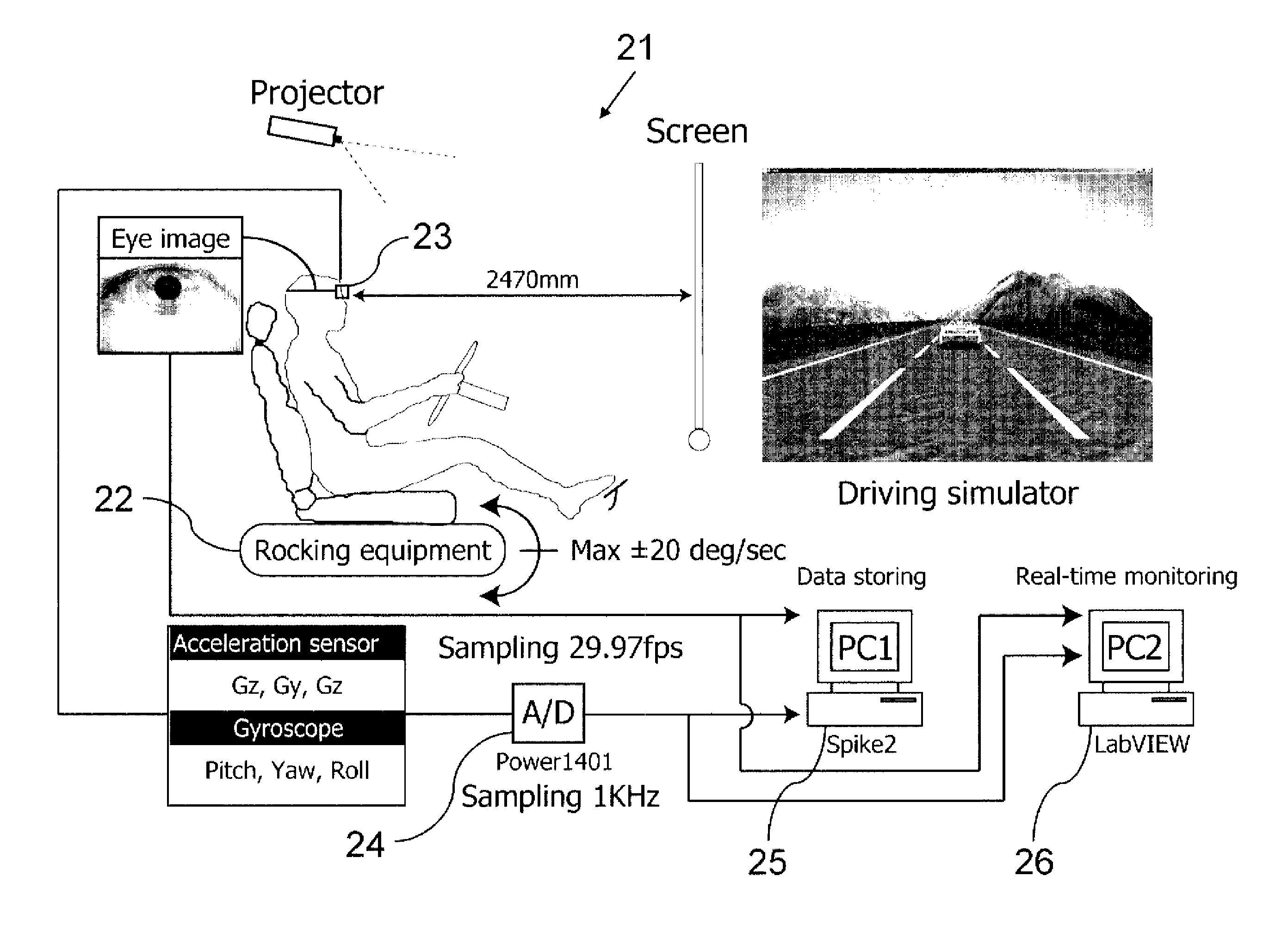
[0051]An example of the present invention is shown below. FIG. 3 shows a schematic diagram of an experimental system simulating automobile driving. A driving simulator (DS) system 21 includes a projector and a screen for projecting DS images and a driver seat with a steering, an accelerator and a brake. The driver seat was installed at a position where the head of a subject and a center of the screen were right opposite to each other. A distance between the front surface of the head of the subject and the screen was 2470 mm, and a screen size was 10 inches (lateral view angle of ±39.1°, vertical view angle of ±26.3°). A vibrating device 22 for inducing vestibule-ocular reflex was installed below the driver seat. The luminance and contrast of the projector were so adjusted that a pupil diameter of the subject is substantially a median diameter (diameter of about 6 mm) of a pupil movable range.

[0052]Both eye images were measured at 29.97 fps by an eye movement scanner 23. Unillustrate...


PUM


Abstract

A sleepiness sign detection apparatus, includes: a head movement detection unit configured to detect a head movement to generate a head movement data; an eye movement detection unit configured to detect an eye movement to generate an eye movement data; an ideal eye movement angular velocity calculation unit configured to calculate an ideal eye movement angular velocity based on the head movement data generated by the head movement detection unit; an eye-rotation angular velocity calculation unit configured to calculate an eye-rotation angular velocity based on the eye movement data generated by the eye movement detection unit; and a sleepiness sign detection unit configured to detect vestibule-ocular reflex (VOR) from the ideal eye movement angular velocity and the eye-rotation angular velocity, and determine a sign of sleepiness based on the vestibule-ocular reflex.

Description

CROSS REFERENCE TO RELATED APPLICATIONS[0001]This is a continuation application of International Patent Application No. PCT / JP2009 / 004572 filed Sep. 14, 2009 claiming priority upon Japanese Patent Application No. 2008-238931 filed Sep. 18, 2008, of which full contents are incorporated herein by reference.BACKGROUND OF THE INVENTION[0002]1. Field of the Invention[0003]The present invention relates to a sleepiness sign detection apparatus for detecting a sign of sleepiness of a vehicle driver and a facility operator before they become aware of sleepiness, by taking advantage of vestibule-ocular reflex induced by a head movement.[0004]2. Description of the Related Art[0005]The objective detection of an arousal level is effective in preventing an accident caused by the reduction in an arousal level of a vehicle driver or a machine operator, i.e. sleepiness. Conventionally, sleepiness detection apparatuses which detect sleepiness by using biological signals such as brain waves, blinking,...

Claims


Application Information

Patent Timeline
Patent Type & Authority Patents(United States)
IPC IPC(8): A61B3/14
CPCA61B3/112A61B3/113A61B5/18A61B5/4809G08B21/06A61B5/1114A61B2562/0219A61B5/163G06V40/19G06V20/597A61B5/11
Inventor HIRATA, YUTAKA
Owner CHUBU UNIV EDUCATIONAL F
Why Eureka
Try Eureka