Semiconductor device
a technology of semiconductor devices and semiconductor components, applied in the direction of amplitude demodulation, transmission, indirect connection of subscribers, etc., can solve the problems of circuits consuming electric power, semiconductor devices themselves could be broken, and the semiconductor device itself could be degraded, so as to reduce the number of components and reduce the number of connections to other circuit components. , the effect of reducing the number of components
- Summary
- Abstract
- Description
- Claims
- Application Information
AI Technical Summary
Benefits of technology
Problems solved by technology
Method used
Image
Examples
embodiment mode 1
(Embodiment Mode 1)
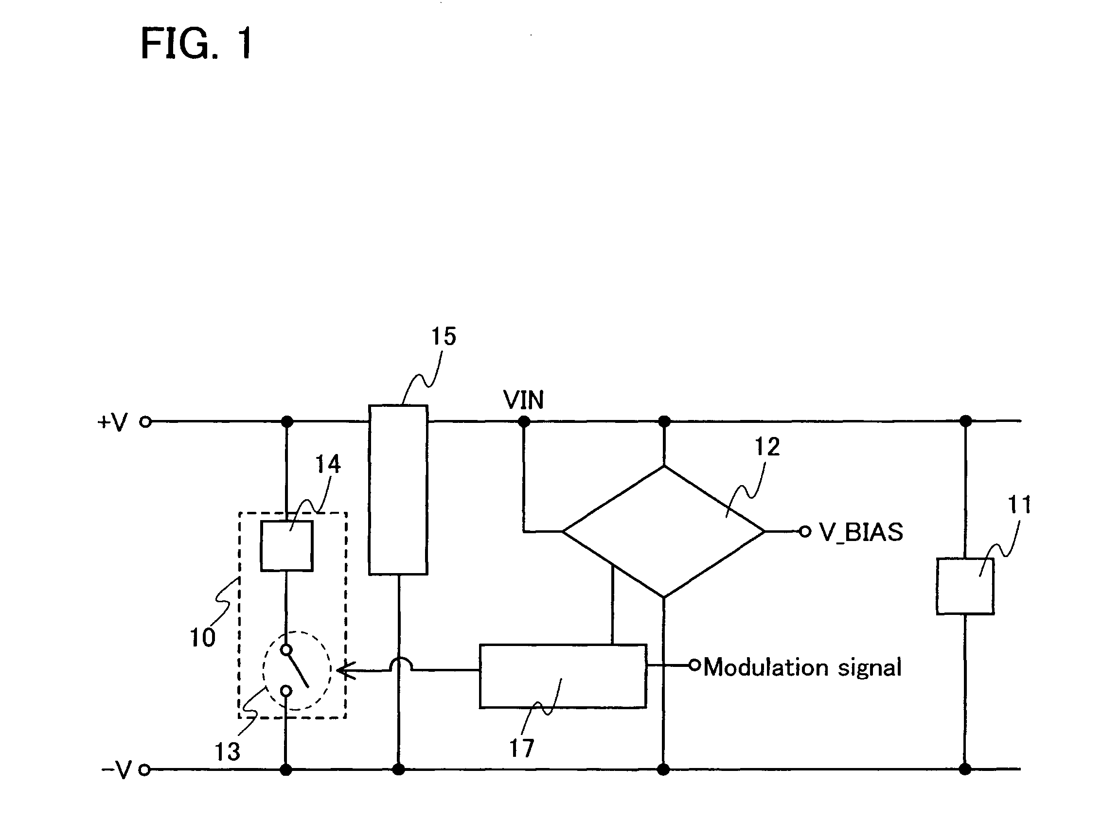
[0042]Embodiment Mode 1 of the present invention will be described with reference to FIG. 1.
[0043]A semiconductor device of the present invention includes a circuit portion 11, a rectifier circuit portion 15, a comparison circuit 12 which is a circuit for comparing input voltage VIN with reference voltage V_BIAS, a bias circuit portion 17 which applies bias voltage (protection signal) to a modulation signal, and a protection / modulation circuit portion 10 having a switch 13 and a load 14, as shown in FIG. 1. Note that the input voltage VIN is generated by the rectifier circuit portion 15.
[0044]In FIG. 1, the comparison circuit 12 outputs voltage in accordance with the input voltage VIN to the bias circuit portion 17, when the input voltage VIN reaches a given value or more. The bias circuit portion 17 applies bias voltage in accordance with the output voltage of the comparison circuit 12 to a modulation signal (adds a protection signal to the modulation signal) and...
embodiment mode 2
(Embodiment Mode 2)
[0054]This embodiment mode will describe a more specific configuration of the semiconductor device shown in the preceding embodiment mode with reference to the drawings.
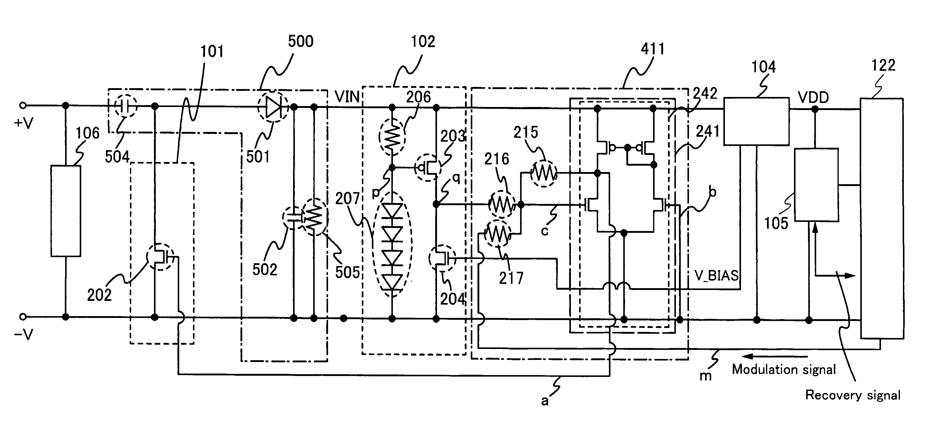
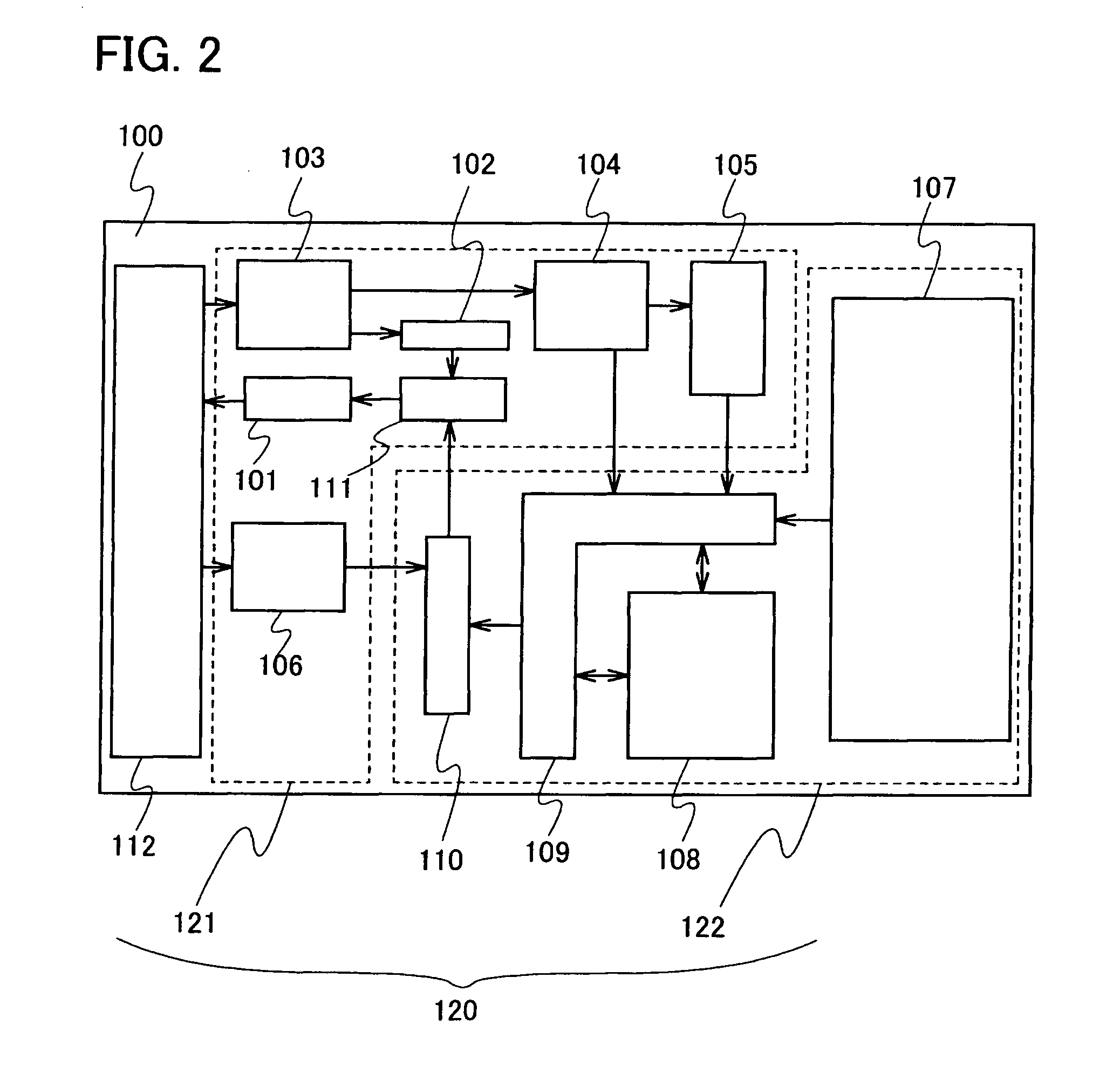
[0055]A semiconductor device 100 shown in this embodiment mode includes an antenna 112 to receive electric power and data from a reader / writer and a chip 120 including an input circuit portion 121 and a logic circuit portion 122 (FIG. 2). Note that the antenna 112 can be manufactured separately from the chip 120 and then connected thereto in another step to form the semiconductor device. Preferably, the antenna 112 and the chip 120 are formed in the same step.
[0056]The input circuit portion 121 of the semiconductor device 100 includes a rectifier circuit portion 103 to convert AC electric power received from the antenna 112 to DC electric power, a constant voltage circuit portion 104 to supply a constant voltage to an internal circuit, a protection / modulation circuit portion 101 to perform modulati...
embodiment mode 3
(Embodiment Mode 3)
[0083]The semiconductor device of the present invention can also have a configuration without the load 201 of FIG. 3, as a variation of the input circuit portion according to Embodiment Mode 2.
[0084]The impedance of the chip 120 can be controlled by voltage applied to the gate electrode of the transistor 202, also when the load 201 is not provided. The amount of current to be applied to the transistor 202 can be estimated by the intended degree of change in impedance of the chip 120. Therefore, the size of the transistor 202 may be determined to be able to supply current in such amount that the impedance of the chip 120 is sufficiently changed.
[0085]Thus, also when the load 201 is not provided, the impedance of the chip 120 can be changed by applying current to the transistor 202, whereby the impedances of the chip 120 and the antenna 112 can intentionally be made not to match each other.
[0086]This embodiment mode can be implemented in combination with technical e...
PUM
 Abstract
Description
Claims
Application Information
 - R&D
- Intellectual Property
- Life Sciences
- Materials
- Tech Scout
- Unparalleled Data Quality
- Higher Quality Content
- 60% Fewer Hallucinations
Browse by: Latest US Patents, China's latest patents, Technical Efficacy Thesaurus, Application Domain, Technology Topic, Popular Technical Reports.
© 2025 PatSnap. All rights reserved.Legal|Privacy policy|Modern Slavery Act Transparency Statement|Sitemap|About US| Contact US: help@patsnap.com


