
Remote switch actuator

a remote switch and actuator technology, applied in the direction of tumbler/rocker switches, contact mechanisms, electrical equipment, etc., can solve the problems of not all electrical arcs are desirable, sudden breakdown of voltage resistance of air, and significant danger created by the toggling of switches, so as to reduce the amount of force applied to the system by the user, reduce the and reduce the effect of time-consuming or bothersome protective measures

Inactive Publication Date: 2013-01-29
THE UNITED STATES AS REPRESENTED BY THE DEPARTMENT OF ENERGY
View PDF3 Cites 7 Cited by
  • Summary
  • Abstract
  • Description
  • Claims
  • Application Information

AI Technical Summary

Benefits of technology

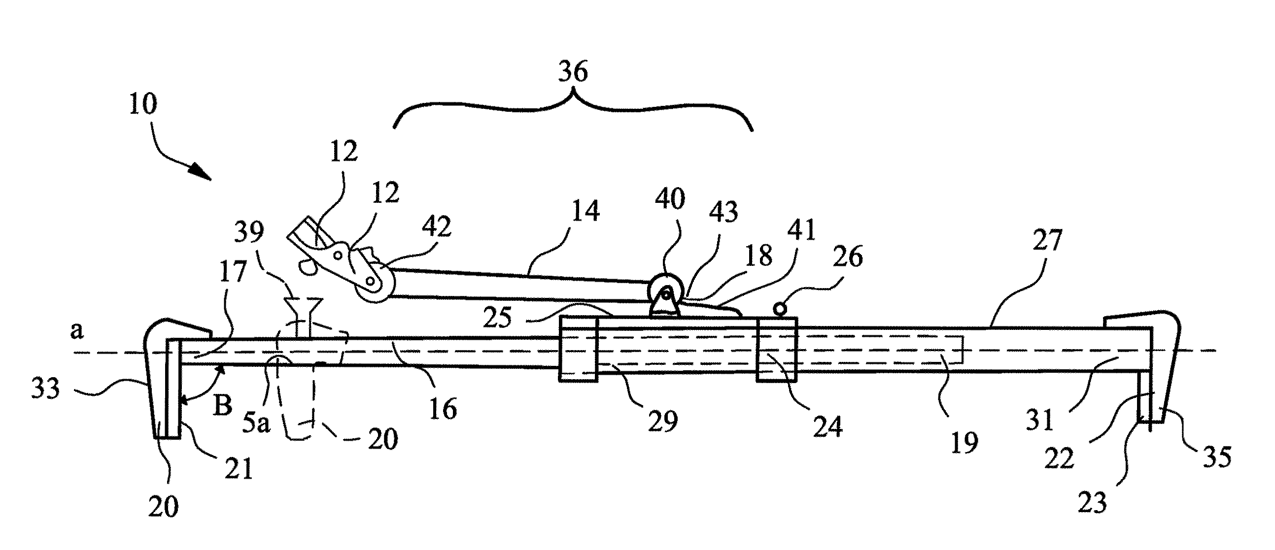
The present invention provides a way to safely actuate switches from a safe distance. It uses a force tether to actuate the switch, which can be used from a distance beyond the danger posed by electrical and pressure-breaching arc flash events. The invention also utilizes an actuation tether that is electrically and / or thermally insulating, meaning operators can wear minimal protective clothing. The invention is adaptable to a variety of switch housing configurations or immobile objects in close spatial relationship to the switch. It increases the force applied by the user, allowing the operator to remotely actuate a switch with less force than would be necessary if the operator was actuating the switch through direct contact. The invention provides a visible indicator of whether the user is too proximate to the switch. Overall, the invention ensures safe operation of switches in various situations.

Problems solved by technology

However, significant danger is created by the toggling of switches associated with high-current circuits.
The danger stems from the sudden breakdown of voltage resistance of the air surrounding the switch.
Electrical arcs have practical uses, such as in welding, plasma cutting, or as a light source; however not all electrical arcs are desirable.
Unintentional electrical arcs formed by high voltage and high current electrical discharges result in particularly dangerous events called arc flashes.
Arc flashes are potentially destructive events releasing large amounts of energy in the form of light and heat.
While arc flashes are possible only in some environments (above 480 Volts (V)), the resulting potential injury and risk of damage is unacceptable.
For example, industrial equipment such as loading devices commonly use three-phase connections resulting in voltage potential differences of at least 480 volts.
If a sufficiently large fault current occurs on such a circuit, the amount of energy released by a resulting arc flash could be catastrophic.
While much of the energy released by an arc flash event (radiant energy) is different from a chemical explosion (mechanical shock), both are highly dangerous inasmuch as both produce significant pressure / shock waves that violently propel solid or molten material outward.
The actuation of electrical switches, such as circuit breakers, is especially prone to arc flash events.
However, as no switch operates instantly, an ungrounded fault current develops prior to the flow of current ceasing.
While it may dissipate harmlessly, arc flashing is also possible resulting in injury to the operator and property damage.
Due to their insulating capacity, the suits are both uncomfortable to wear and are also expensive.
Further, the protective suits require time to don and subsequently remove, even if the switch actuation requires no more than a few seconds.
In environments where the ambient temperatures exceed approximately 60° F., these suits cause the wearers to perspire excessively.
The inconvenience of donning bulky protective suits results in their being used less frequently.

Method used


Image

  • Remote switch actuator
  • Remote switch actuator
  • Remote switch actuator

Examples


Embodiment Construction

[0031]The foregoing summary, as well as the following detailed description of certain embodiments of the present invention, will be better understood when read in conjunction with the appended drawings.

[0032]As used herein, an element or step recited in the singular and proceeded with the word “a” or “an” should be understood as not excluding plural said elements or steps, unless such exclusion is explicitly stated. Furthermore, references to “one embodiment”of the present invention are not intended to be interpreted as excluding the existence of additional embodiments that also incorporate the recited features. Moreover, unless explicitly stated to the contrary, embodiments “comprising” or “having” an element or a plurality of elements having a particular property may include additional such elements not having that property.

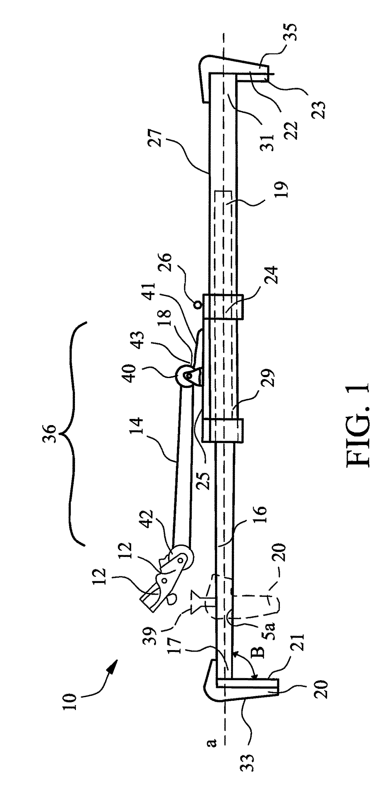
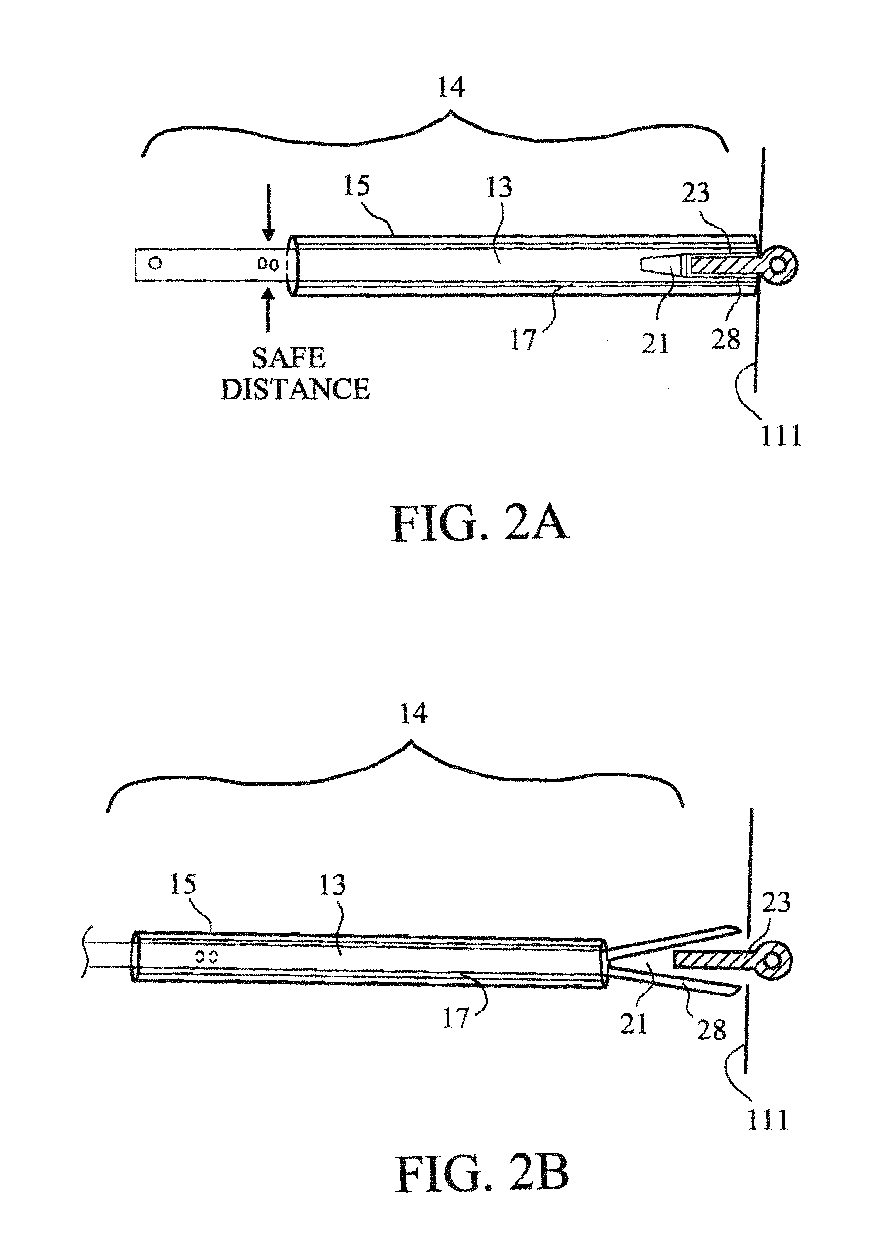
[0033]Turning first to FIG. 1, depicted there is an elevational view of one embodiment of the instant invention. The invention comprises a generally elongated ...


PUM


Abstract

The invention provides a device and method for actuating electrical switches remotely. The device is removably attached to the switch and is actuated through the transfer of a user's force. The user is able to remain physically removed from the switch site obviating need for protective equipment. The device and method allow rapid, safe actuation of high-voltage or high-current carrying electrical switches or circuit breakers.

Description

[0001]The United States Government has rights in this invention pursuant to the employer-employee relationship between the Government and the inventors as U.S. Department of Energy employees at the Brookhaven National Energy Technology Laboratory.BACKGROUND OF THE INVENTION[0002]1. Field of the Invention[0003]This invention relates to a device and method for activating a switch, and in particular, the invention relates to a removable and adjustable switch actuator for remote activation of a switch handle, or toggle, and a method for remote activation of a switch or toggle.[0004]2. Background of the Invention[0005]Toggling or actuation of electrical switches is common place. However, significant danger is created by the toggling of switches associated with high-current circuits. The danger stems from the sudden breakdown of voltage resistance of the air surrounding the switch. Normally, air is a good insulator, however, the resistivity of air may be overcome if air provides the optim...

Claims


Application Information

Patent Timeline
Patent Type & Authority Patents(United States)
IPC IPC(8): H01H3/02
CPCH01H3/02H01H2300/056
Inventor HAAS, EDWIN GERARDBEAUMAN, RONALDPALO, JR., STEFAN
Owner THE UNITED STATES AS REPRESENTED BY THE DEPARTMENT OF ENERGY
Learn More