
Automatic error diagnosis and correction for RTL designs

a technology of error diagnosis and error correction, applied in the field of integrated circuit design, can solve the problems of ineffective application of gate level diagnosis algorithms to rtl, rtl error diagnosis is rather different from that at the gate level, and the described techniques can diagnose significantly more bugs. , to achieve the effect of improving the overall verification quality, facilitating the rtl debugging process, and efficient and scalabl

Inactive Publication Date: 2013-01-29
RGT UNIV OF MICHIGAN
View PDF6 Cites 9 Cited by
  • Summary
  • Abstract
  • Description
  • Claims
  • Application Information

AI Technical Summary

Benefits of technology

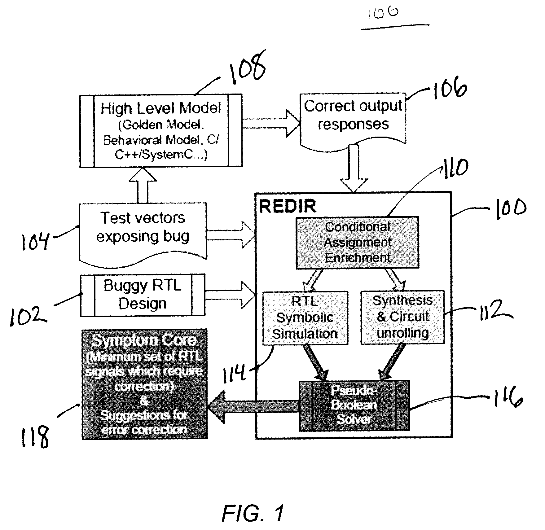
[0011]In this application we propose several constructs and algorithms that provide a new way to diagnose and correct errors at the RTL, including: (1) an innovative RTL error modeling construct; (2) scalable error-diagnosis algorithms using Pseudo-Boolean constraints, synthesis, and simulation; and (3) a novel error-correction technique using signatures. To empirically validate the techniques, we developed a novel verification framework, called REDIR. To this end, our experiments with industrial designs demonstrate that REDIR is efficient and scalable. In particular, designs up to a few thousand lines of code (e.g., 100K cells after synthesis) can be handled within minutes. In addition, the described techniques can diagnose significantly more bugs than state-of-art gate-level approaches. The results indicate that error diagnosis at the RTL is rather different from that at the gate level, and applying gate level diagnosis algorithms to RTL is ineffective. Since the techniques rely on correct output responses and support both combinational and sequential circuits, they can be applied to various designs in all mainstream verification flows. Therefore, the algorithmic techniques and the overall methodology proposed in our work can greatly facilitate the RTL debugging process and improve the overall verification quality.
[0015]Logic and Symbolic Simulation—Logic simulation models the behavior of a digital circuit by propagating scalar Boolean values (0 and 1) from primary inputs to primary outputs. For example, when simulating 2-input AND with both inputs set to 1, the output 1 is produced. On the other hand, symbolic simulation uses symbols instead of scalar values and produces Boolean expressions at the outputs. As a result, simulating a 2-input XOR with inputs a and b generates an expression “a XOR b” instead of a scalar value. To improve scalability, modern symbolic simulators employ several techniques, including approximation, parameterization and on-the-fly logic simplification. For example, with on-the-fly logic simplification, “0 XOR b” is simplified to b thus reducing the complexity of the expression. Traditional symbolic simulators operate on a gate-level model of a design; however, in recent years simulators operating on RTL descriptions have been proposed.
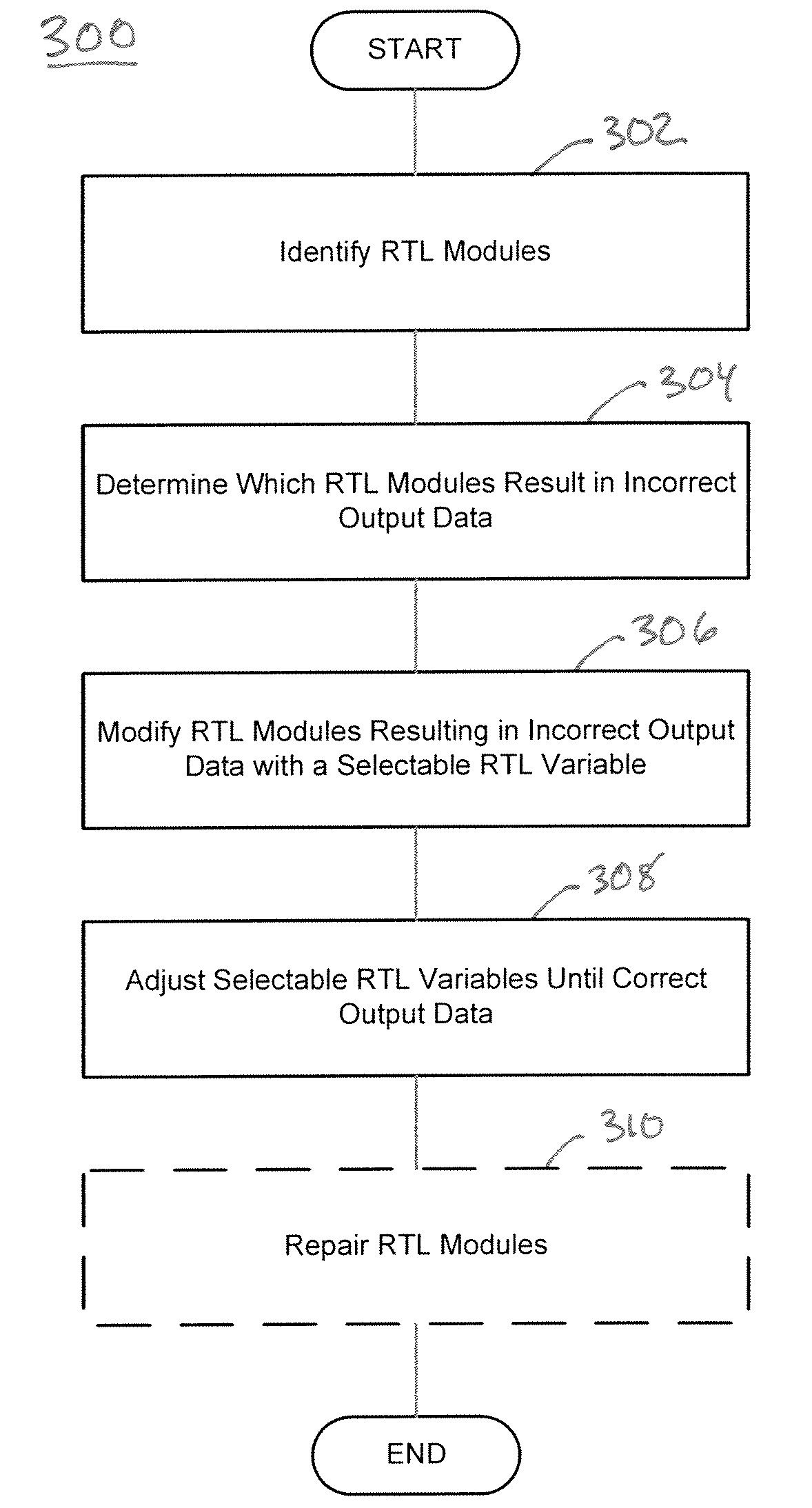
[0017]Whether from a synthesis-based diagnosis, a simulation-based diagnosis, or a combination of both running simultaneously, the present techniques describe a computer executable framework that facilitates integrated circuit design and debugging by working directly at the Register Transfer Level, where most design activities take place. The framework may be executed in software or as an integrated circuit or other application in hardware. The framework determines when an integrated circuit design produces incorrect output responses for a given set of input vectors by comparing the actual responses with the expected responses. The framework accesses the expected responses and returns the signal paths in the integrated circuit that are responsible for the errors along with suggested changes for fixing the errors. The framework may operate at the RTL, which is above the gate level abstraction which means that the design errors will be much more readily understood to the designer, and may improve scalability and efficiency.

Problems solved by technology

In addition, the described techniques can diagnose significantly more bugs than state-of-art gate-level approaches.
The results indicate that error diagnosis at the RTL is rather different from that at the gate level, and applying gate level diagnosis algorithms to RTL is ineffective.

Method used


Image

  • Automatic error diagnosis and correction for RTL designs
  • Automatic error diagnosis and correction for RTL designs
  • Automatic error diagnosis and correction for RTL designs

Examples


example 1

[0058]Assume that the circuit shown (RTL module) in FIG. 6 contains an error: signal g1 is erroneously assigned to expression “r1|r2” instead of “r1& r2”. Conditional assignments, highlighted in boldface, have been inserted into the circuit using the techniques described above. For simplicity reasons, the MUXes at the outputs of registers r1 and r2 are not included. The trace that exposes the error in two simulation cycles consists of the following values for inputs {I1, I2}: {0, 1}, {1, 1}. When the same trace is simulated by a high-level behavioral model, the correct output responses for {O1, O2} are generated: {0, 0}, {1, 0}. Besides these output responses, no addition information, such as values of internal signals and registers, is required. We annotate the symbols injected during the simulation by their cycle numbers using subscripts. The Boolean expressions for the primary outputs for the two cycles of simulation are:

O1n@1=O1sel?O1f@1:[I1@1|(g1sel?g1f@1:0)]

O2n@1=O2sel?O2f@1:[...

example 2

[0067]Using the same circuit as Example 1, the values returned by the PB solver for g1f@0 and g1f@1 are both 0. Since the inputs to g1 are {0, 0} and {0, 1} for the first two cycles, RTL error correction returns the following new logic expressions that can fix the error: g1=r1&r2, g1=r1, etc. Note that although the correct fix is returned, the fix is not unique. In general, longer traces containing various test vectors will identify the error with higher precision and suggest better fixes than short ones.

[0068]Fixing errors involving multi-bit variables is more difficult than fixing errors involving only one-bit variables because different bits in the variable may be generated differently. To solve this problem, the framework 100 may allow the user to insert a conditional assignment for each bit in the variable. Alternatively, the framework 100 can also be configured to consider only the least-significant bit when performing error correction. This is useful when the variable is cons...


PUM


Abstract

A computer executable tool facilitates integrated circuit design and debugging by working directly at the Register Transfer Level, where most design activities take place. The tool determines when an integrated circuit design produces incorrect output responses for a given set of input vectors. The tool accesses the expected responses and returns the signal paths in the integrated circuit that are responsible for the errors along with suggested changes for fixing the errors. The tool may operate at the RTL, which is above the gate-level abstraction which means that the design errors will be much more readily understood to the designer, and may improve scalability and efficiency.

Description

CROSS-REFERENCE TO RELATED APPLICATION[0001]The present application claims the benefit of U.S. Provisional Application No. 60 / 940,290, entitled “Automatic Error Diagnosis and Correction for RTL Designs,” filed on May 25, 2007, which is hereby incorporated by reference herein in its entirety.BACKGROUND OF THE DISCLOSURE[0002]1. Field of the Disclosure[0003]The disclosure relates generally to integrated circuit design and, more particularly, to techniques for detecting and correcting errors in integrated circuit design.[0004]2. Brief Description of Related Technology[0005]The dramatic increase in design complexity of modern electronics challenges the ability of developers to ensure their functional correctness. While improvements in verification allow engineers to find a larger fraction of design errors more efficiently, little effort has been devoted to fixing such errors. As a result, debugging remains an expensive and challenging task.[0006]To address this problem, researchers have...

Claims


Application Information

Patent Timeline
Patent Type & Authority Patents(United States)
IPC IPC(8): G06F9/455G06F17/50
CPCG06F17/5045G06F30/30
Inventor CHANG, KAI-HUIWAGNER, ILYAMARKOV, IGORBERTACCO, VALERIA
Owner RGT UNIV OF MICHIGAN
Learn More