Particle-optical system

a particle-optical and multi-column technology, applied in the field of multi-beamlet multi-column particle-optical systems, can solve problems such as deteriorating imaging performance, and achieve the effects of reducing heat and/or charge accumulation, uniform and more precise machining, and enhancing adhesion of thin films

Inactive Publication Date: 2013-02-05
CARL ZEISS SMT GMBH
View PDF23 Cites 7 Cited by
  • Summary
  • Abstract
  • Description
  • Claims
  • Application Information

AI Technical Summary

Benefits of technology

[0018]In exemplary embodiments, the first distance is by at least about 5% smaller than the second distance, in further exemplary embodiments by at least about 10%, for instance at least about 15% or 20% smaller. The difference between the first and second distances is indicative of a deviation of the shape of the aperture from the ideal circular shape, or a contribution of additional shape features, which difference enables the provision of a desired field shaping or field correcting effect.
[0029]In preferred embodiments, and in line with the teaching of US 2005 / 0072933 A1, as mentioned above, in the at least one of the plurality of charged particle multi-beamlet columns, the electrostatic lens arrangement comprises two or more electrode elements which are disposed coaxially and spaced apart, i.e. in series, in the direction of the optical axis. Providing a series of coaxially aligned electrode elements allows improved shielding of a space inside the electrode elements, as mentioned in connection with the disclosure of the above-cited patent application. In exemplary embodiments, three or more than three electrode elements are provided. In further exemplary embodiments, the majority or all of the plurality of multi-beamlet particle-optical columns comprise two or more electrode elements, for instance three or four and more electrode elements. Each electrostatic lens arrangement of the plurality of multi-beamlet particle-optical columns may comprise the same number of electrode elements. Further more, the electrostatic lens arrangements of the plurality of multi-beamlet particle-optical columns may be substantially the same or may be different in terms of configuration, such as a number of electrode elements, a distance of electrode elements from one another, a position of the electrostatic lens arrangement within the column and other parameters, as will be readily apparent to the skilled person.
[0039]In preferred embodiments of the particle-optical system according to the present invention, at least two columns, preferably all of the columns of the plurality of columns, have electrostatic lens arrangements with an electrode element comprised therein which is disposed in a plane spaced at a predetermined distance from a substrate plane, with said plane preferably being arranged parallel to the substrate plane. Further, in those preferred embodiments, the electrode elements which are comprised in neighbouring columns and which are disposed in said plane may be arranged on a common mounting structure, which mounting structure preferably would be substantially disposed in or at least parallel to said plane, and preferably orthogonal to the optical axes of the neighbouring columns. An individual electrode element or at least a portion thereof, such as an annular inner member, as referred to above, may be inserted into, fixed to, rested on or otherwise held by the mounting structure. For instance, the mounting structure may be an electrode element mounting plate, which mounting plate may comprise openings for the individual electrode elements or portions / members thereof. The electrode elements may be manufactured independently from the mounting structure or be integrally formed with the mounting structure. Use of a mounting structure has an advantage in that it facilitates positioning electrode elements of electrostatic lens arrangement of neighbouring columns to be suitably positioned, in particular positioned such that they all have the same distance from the substrate plane and are thus disposed in the same plane.
[0042]In particular in those embodiments of the present invention wherein the electrostatic lens arrangement of at least one column comprises two or more electrode elements, the electrode elements may, in addition to an annular inner electrode member, for instance, comprise a substantially cylindrical shielding member, the substantially cylindrical shielding member preferably having a radius equal to or greater than the second distance. The shielding member may be disposed in a gap between electrode elements disposed adjacent to one another along the optical axis so as to further prevent interferences from an outside of the respective column in a space inside the electrostatic lens arrangement. The shielding member may be a cylinder, which is arranged coaxially with the optical axis and extends at least over an axial portion of the gap between respective portions of adjacent electrode elements. Dimensions and location of said portion would be chosen such that no electrical shortcuts are generated in between the adjacent electrode elements. In those embodiments of the present invention wherein first electrode elements are mounted on a first mounting structure and second electrode elements on a second mounting structure, and wherein the electrode elements comprise at least an annular inner electrode member and a shielding member, the inner electrode member may be disposed such as to substantially extend on one side of the mounting structure, as seen in a direction of the optical axis, and the shielding element such as to extend substantially on the other (opposite) side of the mounting structure. For instance, the shielding element may be disposed substantially upstream of the mounting structure and the inner electrode member such that it extends substantially downstream of the mounting structure.
[0049]Those embodiments that comprise two or more mounting structures, the mounting structures may be built as stiff cages having ceramic insulators disposed between them. The mounting structures may be soldered together. The electrode elements may be machined / subjected to further fine processing after having been mounted to the mounting structure to allow for a uniform and more precise machining of all electrode elements mounted in the same plane and to the same mounting structure.
[0050]The electrodes may be made from soft magnetic material, for instance, such as soft iron or permalloy. Furthermore, the electrodes may be coated with a suitable coating, such as thin films of well conducting materials. In exemplary embodiments, a thin film, such as a thin film of titanium, gold, platinum, or any other precious metal may be provided. In alternative embodiments, a homogeneous thin film of carbon may also be used. In addition to the thin film, a bonding agent may be used to enhance adhesion of the thin film to the surface of the multi-aperture plate, for example a thin film of bonding agent may be used in between the plate surface and the thin metal film. As an example, Cr, W or Pt, or any suitable combination thereof, may be used as a bonding agent. These exemplary embodiments are advantageous for protecting the electrode surface from contaminations, in particular when a potential is applied, and may assist in decreasing heat and / or charge accumulating on a respective surface or avoiding oxidation thereof.

Problems solved by technology

In multi-column systems, additional problems arise from the close arrangements of individual columns and their electrostatic and / or electromagnetic fields, which may cause interferences in neighbouring columns.
These interferences, for instance a disturbance of a focussing electrostatic and / or electromagnetic field, may cause imaging errors such as particle-optical aberrations and thus deteriorate an imaging performance.

Method used


Image

  • Particle-optical system
  • Particle-optical system
  • Particle-optical system

Examples


Embodiment Construction

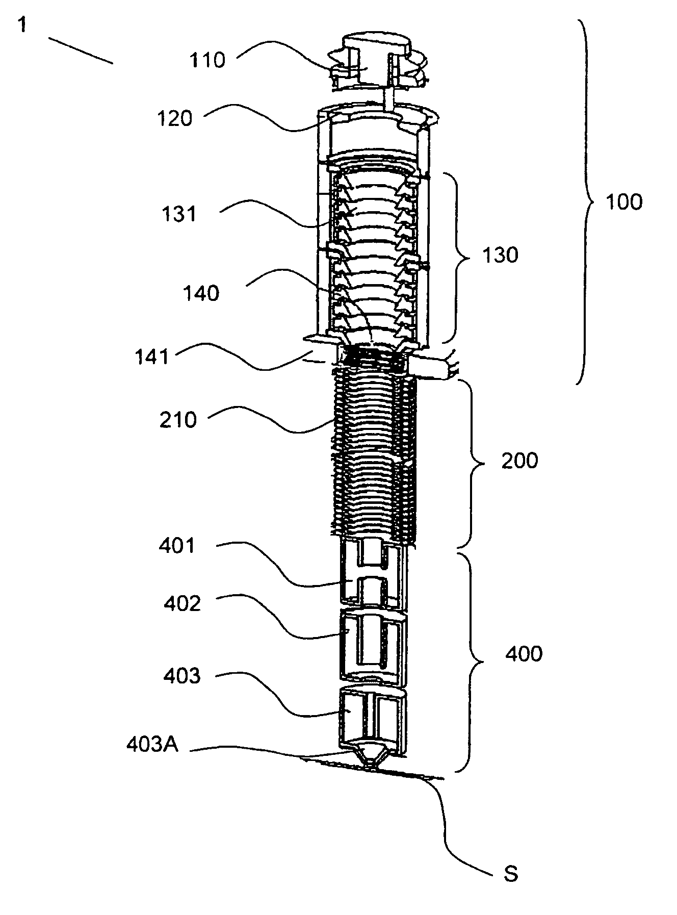
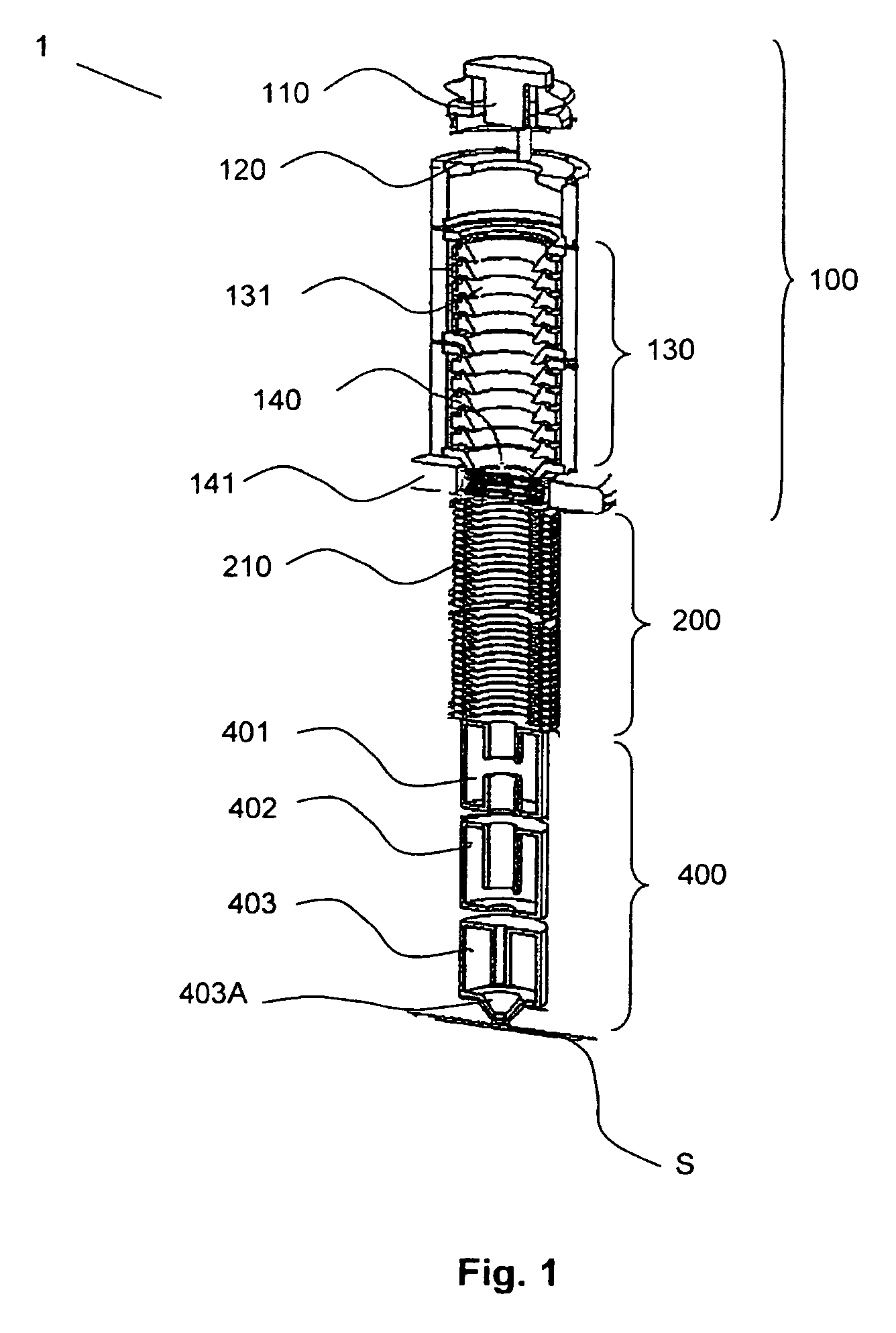
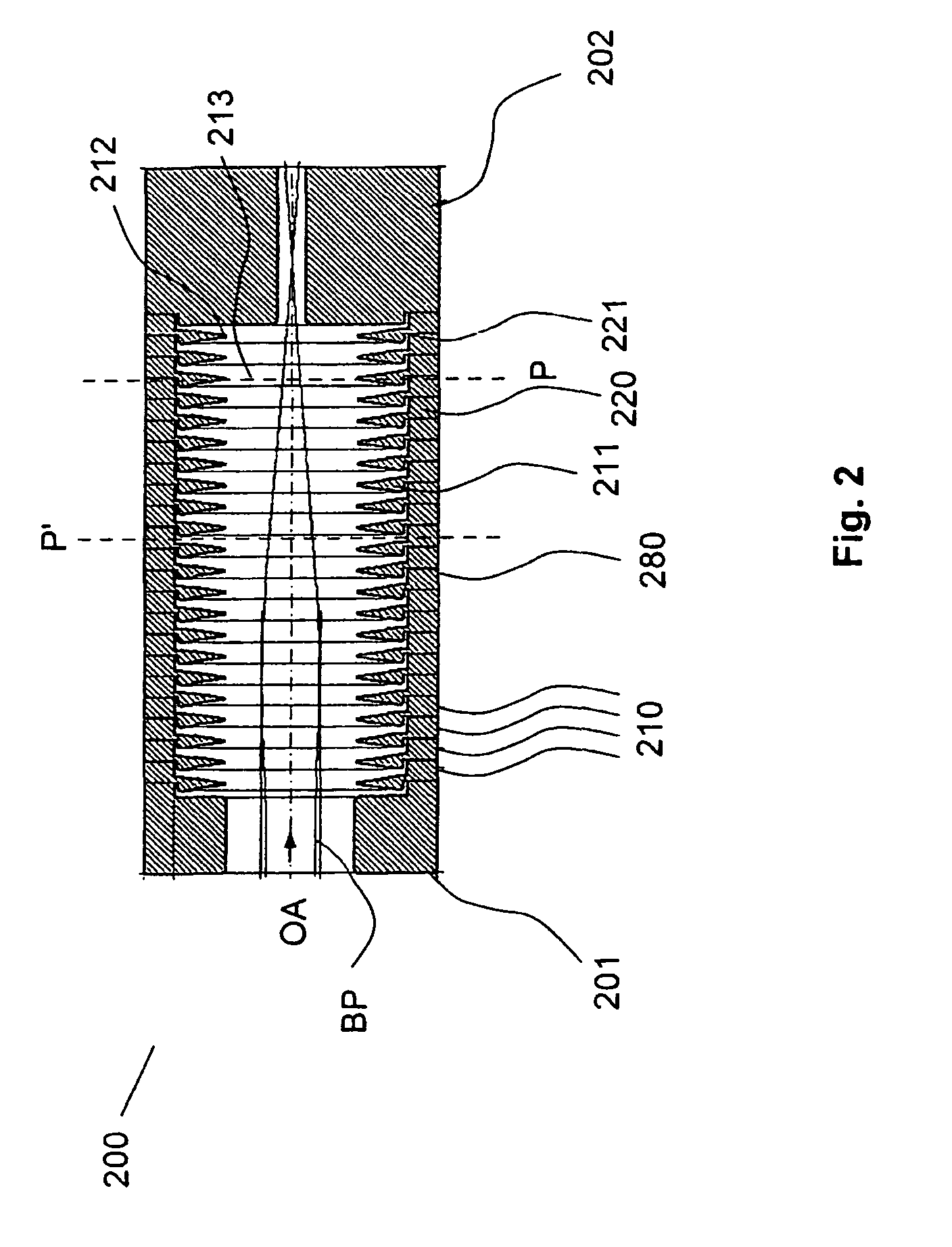
[0062]In FIG. 1, particle-optical components of an embodiment of multi-beamlet particle-optical column 1 for use in a multi-column, multi-beamlet particle-optical system according to the present invention are illustrated. In the depicted embodiment, column 1 comprises, in a direction in which the charged particles would generally travel, a beamlet generating arrangement 100, electrostatic lens 200 and electromagnetic focussing lens arrangement 400. Beamlet generating arrangement 100 comprises charged particle source 110, extraction system 120 and condenser lens 130. The condenser lens 130 comprises a stack of electrodes 131. The beamlet generating system further comprises beam-patterning structure 141 held by a mounting frame 141. The beam patterning structure 141 generally comprises a multi-aperture plate, and may be a blanking aperture array, for instance, as described above. The electrostatic lens arrangement 200 comprises a plurality of electrode elements 210 which are arranged ...


PUM

PropertyMeasurementUnit
distanceaaaaaaaaaa
distanceaaaaaaaaaa
distanceaaaaaaaaaa

Abstract

The present invention relates to a multi-beamlet multi-column particle-optical system comprising a plurality of columns which are disposed in an array for simultaneously exposing a substrate, each column having an optical axis and comprising: a beamlet generating arrangement comprising at least one multi-aperture plate for generating a pattern of multiple beamlets of charged particles, and an electrostatic lens arrangement comprising at least one electrode element; the at least one electrode element having an aperture defined by an inner peripheral edge facing the optical axis, the aperture having a center and a predetermined shape in a plane orthogonal to the optical axis; wherein in at least one of the plurality of columns, the predetermined shape of the aperture is a non-circular shape with at least one of a protrusion and an indentation from an ideal circle about the center of the aperture.

Description

BACKGROUND OF THE INVENTION[0001]1. Field of the Invention[0002]The invention relates to a multi-beamlet multi-column particle-optical system, in particular a multi-beamlet multi-column particle-optical system comprising a plurality of multi-beamlet particle-optical columns wherein at least one of the multi-beamlet particle-optical columns comprises an electrode element having an aperture of a noncircular shape. The invention further relates to a method of exposing a substrate by multi-beam multi-column exposure using the multi-beamlet multi-column particle-optical system.[0003]2. Brief Description of Related Art[0004]The increasing demand for ever smaller and more complex microstructured devices and the continuing demand for an increase of a throughput in the manufacturing and inspection processes thereof have been an incentive for the development of particle-optical systems that use multiple charged particle beamlets in place of a single charged particle beam, thus significantly i...

Claims


Application Information

Patent Timeline
Patent Type & Authority Patents(United States)
IPC IPC(8): G01N23/00G21K7/00
CPCB82Y10/00B82Y40/00H01J37/12H01J37/3177
Inventor PLATZGUMMER, ELMARSTENGL, GERHARDFALKNER, HELMUT
Owner CARL ZEISS SMT GMBH
Why Eureka
Try Eureka