Surface acoustic wave device

a surface acoustic wave and waveguide technology, applied in piezoelectric/electrostrictive/magnetostrictive devices, piezoelectric/electrostriction/magnetostriction machines, electrical apparatus, etc., can solve the problem of difficulty in broadening the bandwidth, and achieve the effect of reducing propagation loss, sufficiently increasing electromechanical coupling coefficient k2, and further improving filter properties

Active Publication Date: 2013-02-12
MURATA MFG CO LTD
View PDF15 Cites 5 Cited by
  • Summary
  • Abstract
  • Description
  • Claims
  • Application Information

AI Technical Summary

Benefits of technology

[0007]Preferred embodiments of the present invention provide a surface acoustic wave device capable of eliminating the above-described defects of the former technique and sufficiently reducing insertion loss.
[0013]The cut angle of the LiTaO3 is preferably in the range of about 36° to about 49°, for example. Therefore, the propagation loss can be further reduced. For example, when used as a band-pass filter, the filter property can be further improved.
[0014]According to the surface acoustic wave device according to the first preferred embodiment of the present invention, the IDT electrode in which the Pt film having the specific film thickness and the Al film having the specific film thickness are laminated is provided. Furthermore, the normalized film thickness of the dielectric layer is preferably within the specific range. Therefore, the electromechanical coupling coefficient k2 can be sufficiently increased. For example, when used as a band-pass filter, an improvement of the filter property, particularly broadening of the bandwidth, can be achieved. In addition, the insertion loss can be sufficiently reduced and the reflection coefficient of the IDT electrode can be increased.
[0015]According to the surface acoustic wave device according to the second preferred embodiment of the present invention, the IDT electrode in which the Au film having the specific film thickness and the Al film having the specific film thickness are laminated is provided. Furthermore, the normalized film thickness of the dielectric layer is preferably within the specific range. Therefore, the electromechanical coupling coefficient k2 can be sufficiently increased. For example, when used as a band-pass filter, an improvement of the filter property, particularly broadening of the bandwidth, can be achieved. In addition, the insertion loss can be sufficiently reduced and the reflection coefficient of the IDT electrode can be increased.
[0016]According to the surface acoustic wave device according to the third preferred embodiment of the present invention, the IDT electrode in which the Ag film having the specific film thickness and the Al film having the specific film thickness are laminated is provided. Furthermore, the normalized film thickness of the dielectric layer is preferably within the specific range. Therefore, the electromechanical coupling coefficient k2 can be sufficiently increased. For example, when used as a band-pass filter, an improvement of the filter property, particularly broadening of the bandwidth can be achieved. In addition, the insertion loss can be sufficiently reduced and the reflection coefficient of the IDT electrode can be increased.
[0017]According to the surface acoustic wave device according to the fourth preferred embodiment of the present invention, the IDT electrode in which the Cu film having the specific film thickness and the Al film having the specific film thickness are laminated is provided. Furthermore, the normalized film thickness of the dielectric layer is preferably controlled to be in the specific range. Therefore, the electromechanical coupling coefficient k2 can be sufficiently increased. For example, when used as a band-pass filter, an improvement of the filter property, particularly broadening of the bandwidth can be achieved. In addition, the insertion loss can be sufficiently reduced and the reflection coefficient of the IDT electrode can be increased.

Problems solved by technology

When used as a band-pass filter, it has been difficult to broaden the bandwidth.

Method used


Image

  • Surface acoustic wave device
  • Surface acoustic wave device
  • Surface acoustic wave device

Examples


Embodiment Construction

[0035]Hereinafter, the present invention is clarified by describing specific preferred embodiments thereof with reference to the drawings.

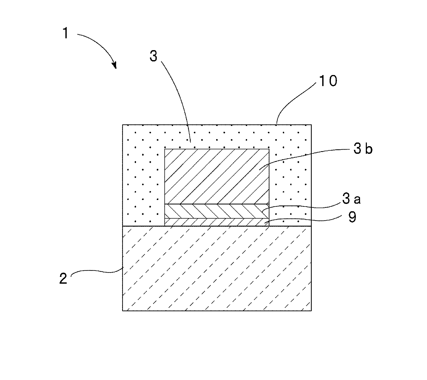
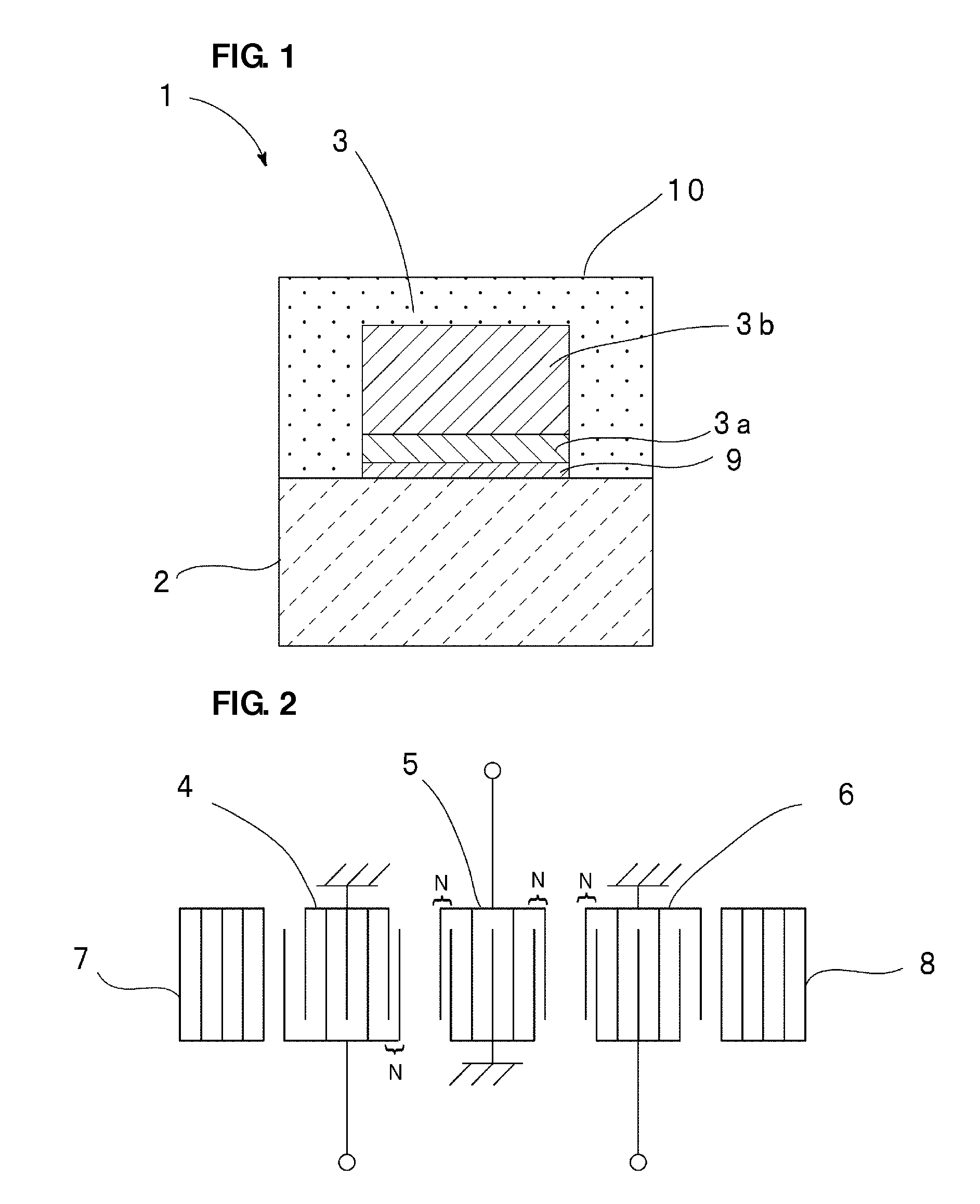
[0036]FIG. 1 is a schematically cross sectional view of a surface acoustic wave device according to one preferred embodiment of the present invention. FIG. 2 is a schematic plan view illustrating the electrode structure thereof.

[0037]As illustrated in FIG. 1, the surface acoustic wave device 1 of this preferred embodiment includes a piezoelectric substrate 2. The piezoelectric substrate 2 preferably is a 44.5° Y—X LiTaO3 substrate in this preferred embodiment. On the piezoelectric substrate 2, an electrode 3 is provided. As the electrode 3, the electrode structure illustrated in FIG. 2 is provided. More specifically, first to third IDT electrodes 4, 5, and 6 are arranged in the surface acoustic wave propagation direction. The IDT electrode 4, 5, or 6 includes electrode fingers which are interpolated to each other. At both sides of a region where t...


PUM


Abstract

A surface acoustic wave device includes an electrode and a dielectric layer laminated on a piezoelectric substrate, in which the electrode includes a first electrode film containing Pt, Au, Ag, or Cu and a second electrode film containing Al, the normalized film thickness h / λ of the first electrode film is about 0.005 or more and at most about 0.015 in the case of Pt, the normalized film thickness h / λ of the Al film is about 0.06 or more and at most about 0.185, and the normalized film thickness h / λ of the dielectric layer is about 0.2 or less.

Description

BACKGROUND OF THE INVENTION[0001]1. Field of the Invention[0002]The present invention relates to a surface acoustic wave device for use in a resonator, a band-pass filter, or other suitable component. More specifically, the present invention relates to a surface acoustic wave device in which an IDT electrode and a dielectric film are disposed on a piezoelectric substrate.[0003]2. Description of the Related Art[0004]Surface acoustic wave devices have been widely used as a resonator or a band-pass filter of communication apparatuses heretofore.[0005]For example, the following Japanese Unexamined Patent Application Publication No. 2008-522514 discloses a surface acoustic wave device in which an IDT electrode and a dielectric film containing SiO2 are laminated on a piezoelectric substrate. Japanese Unexamined Patent Application Publication No. 2008-522514 discloses that the temperature characteristics can be improved by forming the SiO2 film so as to cover the IDT electrode to thereby r...

Claims


Application Information

Patent Timeline
Patent Type & Authority Patents(United States)
IPC IPC(8): H03H9/25
CPCH03H9/0071H03H9/14582H03H9/14544H03H9/14541
Inventor NAKAHASHI, NORIHIKO
Owner MURATA MFG CO LTD
Why Eureka
Try Eureka