Infrared detector

a detector and infrared technology, applied in the field of infrared detectors, can solve the problems of relatively high technology required to fabricate and maintain a vacuum environment for conventional bolometer detectors, and achieve the effects of reducing manufacturing costs over discrete components, facilitating fabrication, and reducing the cost of pir detection modules

Inactive Publication Date: 2013-02-12
FLIR SYSTEMS TRADING BELGIUM BVBA
View PDF41 Cites 2 Cited by
  • Summary
  • Abstract
  • Description
  • Claims
  • Application Information

AI Technical Summary

Benefits of technology

[0048]Preferably, the passive infrared (PIR) alarm comprises a single substrate having the bolometer detectors, the bias means, the connecting means and the signal processing means integrated thereon. An integrated PIR alarm facilitates fabrication and therefore reduces manufacturing costs over discrete components. Accordingly, the passive infrared (PIR) alarm may comprise a monolithic integrated circuit and in particular a silicon monolithic integrated circuit. The monolithic integrated circuit may be one of an n-channel MOSFET (NMOS) integrated circuit, a p-channel MOSFET (PMOS) integrated circuit and a complementary MOSFET (CMOS) integrated circuit.
[0049]Using the silicon based approach it is feasible to integrate a complete PIR detection system (e.g. amplification, detection thresholds, timing functions) onto the same chip as the detectors themselves, thus allowing much smaller and cheaper PIR detection modules to be made. The use of the accurate lithography means that a bolometer based PIR detector can have a very precisely defined size, position and shape.
[0050]In addition it is possible to integrate the full functionality of the PIR sub-system onto the detector chip, offering lower overall cost.

Problems solved by technology

The technology required to fabricate and maintain a vacuum environment for conventional bolometer detectors is relatively expensive.

Method used


Image

  • Infrared detector
  • Infrared detector
  • Infrared detector

Examples


Embodiment Construction

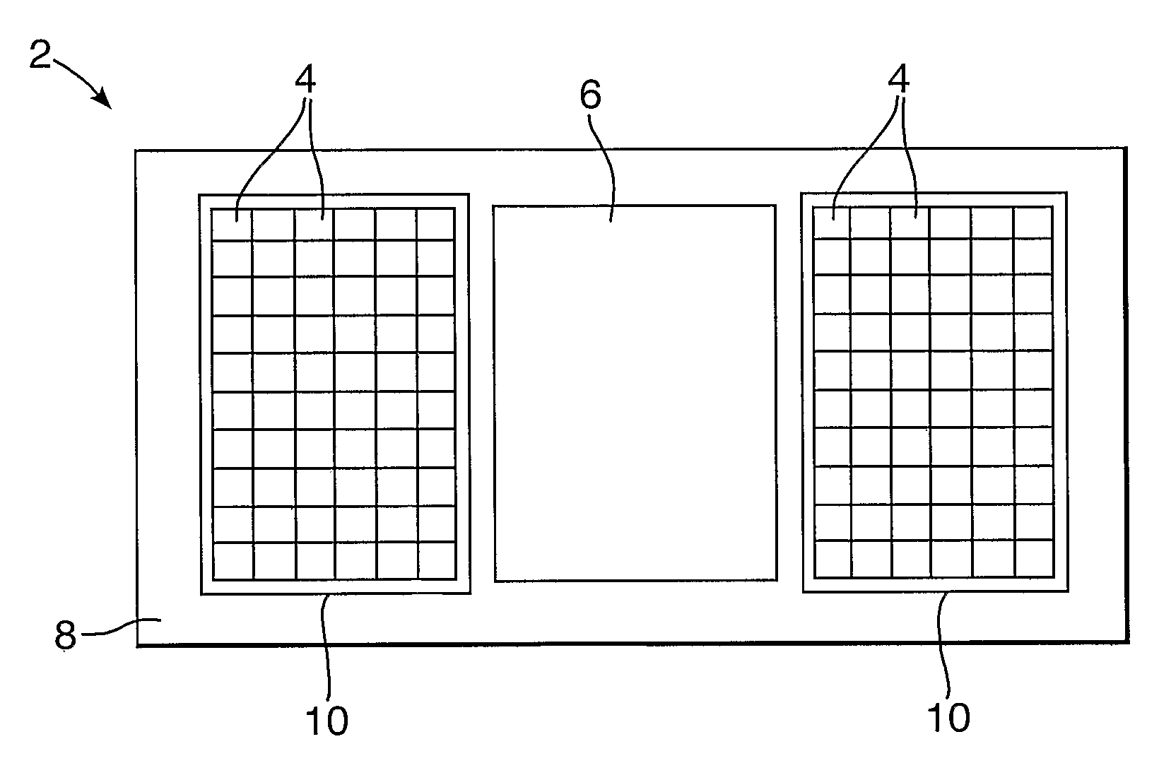
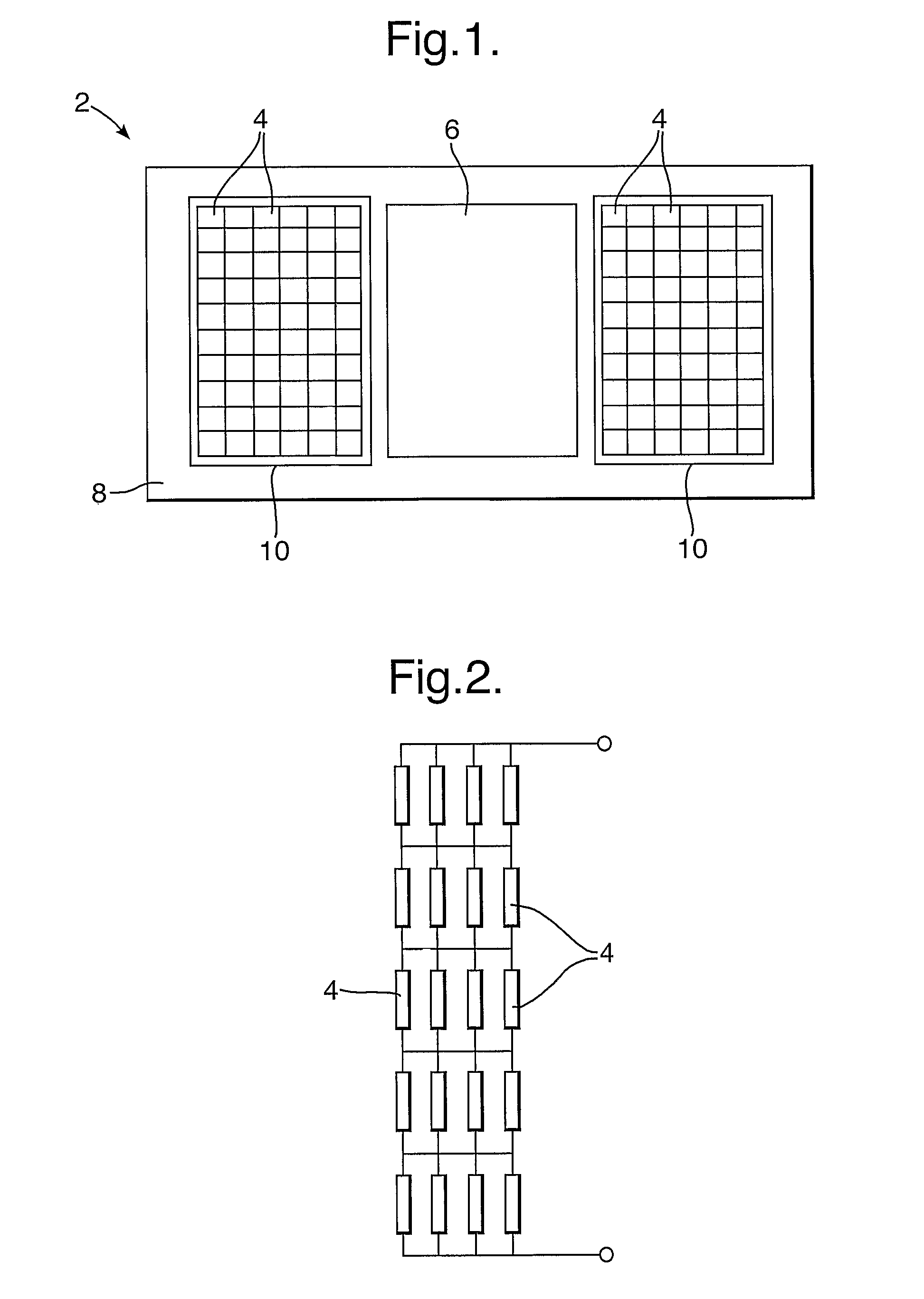
[0060]Conventional bolometer detectors are not considered as a credible alternative to conventional PZT PIR detectors on grounds of disparate technical performance and high cost. One of the main cost drivers is the packaging technology required to provide an evacuated, hermetically sealed enclosure around the bolometer detector(s). In the present infrared detector, the bolometer detectors are operated in an environment (e.g. air) at substantially atmospheric pressure, thereby eliminating the expensive vacuum packaging. Conduction of thermal energy away from a bolometer detector is higher in air than in a vacuum, resulting in reduced sensitivity of the infrared detector. However, in the present invention, the reduction in sensitivity is at least partly compensated by combining a plurality of bolometer detectors together in a network and / or operating the bolometer detectors at a high bias power / current.

[0061]Referring now to a first embodiment of the invention, FIG. 1 shows an infrare...


PUM


Abstract

An infrared detector comprising a plurality of bolometer detectors, bias circuitry for applying a bias to the bolometer detectors, and connectors for connecting the bolometer detectors together to form a network, wherein the bolometer detectors are arranged in an environment at substantially atmospheric pressure. A method for increasing the sensitivity of an infrared detector, having a plurality of bolometer detectors arranged in an environment at substantially atmospheric pressure so as to at least partly compensate for a reduction in the sensitivity of the infrared detector due to conduction of thermal energy from the bolometer detectors through the environment, the method comprising at least one of the steps of connecting the bolometer detectors together in at least one of series and parallel, and operating the bolometer detectors at a DC bias current.

Description

[0001]This application is the U.S. national phase of international application PCT / GB2005 / 004354 filed 11 Nov. 2005, which designated the U.S. and claims benefit of GB 0424934.8 filed 12 Nov. 2004, the entire contents of each of which are hereby incorporated by reference.BACKGROUND OF THE INVENTION[0002]1. Field of the Invention[0003]The present invention relates to an infrared detector, and in particular to a passive infrared (PIR) detector. Such infrared detectors find application in intruder detection systems and fire alarms.[0004]2. Discussion of Prior Art[0005]By way of background to the present invention, conventional passive infrared (PIR) detectors typically utilise pyroelectric detector elements comprising a lead-based ceramic material, for example lead zirconate titanate (PZT). The lead-based ceramic material used within the detector elements is relatively easy to process and the associated manufacturing technology is mature. Many tens of millions of PIR detectors are made...

Claims


Application Information

Patent Timeline
Patent Type & Authority Patents(United States)
IPC IPC(8): G08B13/18G08B17/10H01L25/00G01J5/00G08B17/12G01J5/02G01J5/24G08B13/19
CPCG01J5/24G08B13/19H01L2924/0002H01L2924/00G01J5/02G01J1/42
Inventor MANNING, PAUL A
Owner FLIR SYSTEMS TRADING BELGIUM BVBA
Why Eureka
Try Eureka