High-power-capable circularly polarized patch antenna apparatus and method

a patch antenna and high power capacity technology, applied in the field of single-feed circularly polarized broadband patch antennas, can solve the problems of narrow bandwidth capability, excessive cost, and severe performance limitation of particular design, and achieve the effects of high broadcast transmitter power, broad bandwidth capability, and low cos

Inactive Publication Date: 2013-02-12
DIELECTRIC
View PDF10 Cites 181 Cited by
  • Summary
  • Abstract
  • Description
  • Claims
  • Application Information

AI Technical Summary

Benefits of technology

[0012]The foregoing disadvantages are overcome, to a great extent, by the invention, wherein in one aspect an antenna is provided that in some embodiments of the invention affords lower cost, broad bandwidth capability, support for high broadcast transmitter power, low wind loading, and strong circular polarization in a directional panel antenna.

Problems solved by technology

This particular design is severely limited in performance, however; see, for discussion, Antenna Engineering Handbook, Third Edition, R. C. Johnson, ed., McGraw-Hill, New York, 1993, pp.
Deficiencies in existing antenna designs for the 700 MHz band include excessive cost, narrow bandwidth capability (i.e., low voltage standing wave ratio (VSWR) does not extend over the entire allotted band, or even a substantial fraction thereof), lack of support for high broadcast transmitter power, uncertain wind load, and limited ability to provide circular polarization, in a directional panel antenna.
The complexity of these styles of antennas can result in high cost for the achieved performance.

Method used


Image

  • High-power-capable circularly polarized patch antenna apparatus and method
  • High-power-capable circularly polarized patch antenna apparatus and method
  • High-power-capable circularly polarized patch antenna apparatus and method

Examples


Embodiment Construction

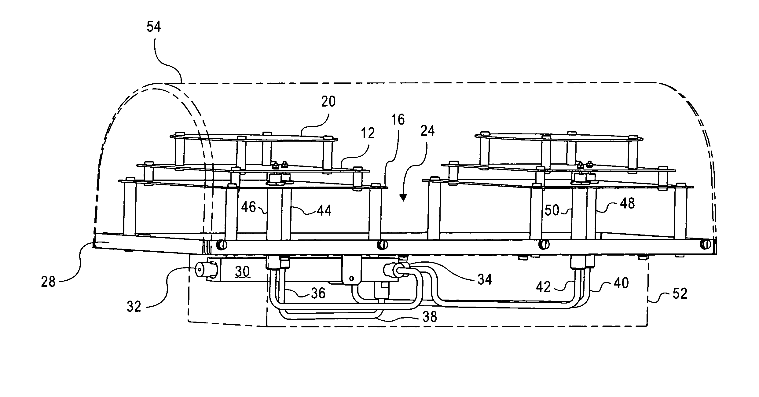
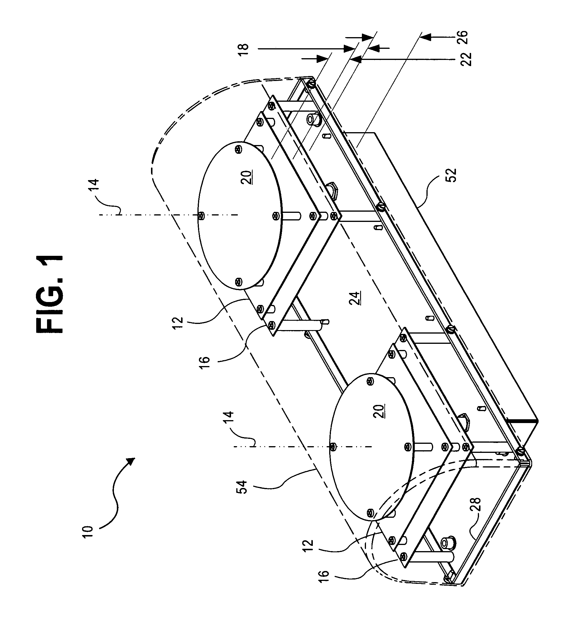
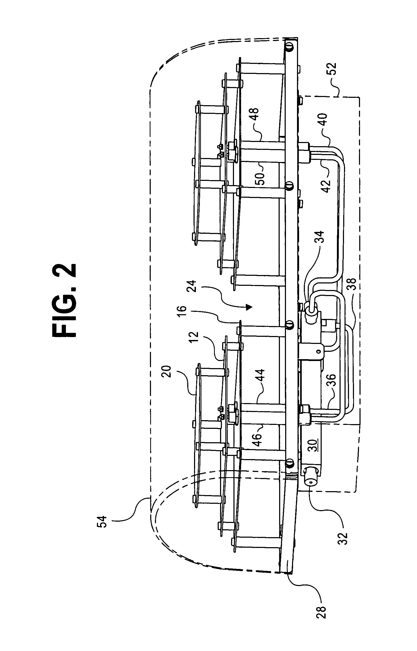
[0029]The invention will now be described with reference to the drawing figures, in which like reference numerals refer to like parts throughout. The invention provides an apparatus and method that in some embodiments provides a patch antenna for the lower 700 MHz band that emits a substantially single beam, circularly-polarized propagation pattern with high gain and relatively high power handling capability.

[0030]Typical patch antennas achieve directionality and impedance control in part by including a backing conductor. Without a backing conductor, a patch radiator exhibits an intrinsic property of emitting similar lobes before and behind (i.e., in the zero-azimuth and 180 degree-azimuth directions, with comparable elevation), known as a peanut pattern, and has an impedance that is a function of patch size and interaction with nearby conductors or free space. Square patches are commonly edge driven or center driven, as determined by the desired radiation pattern and by limitations...


PUM


Abstract

A circularly polarized patch antenna uses a square quarter-wavelength conductive plate, spaced away from a slightly larger backing conductor. Excitation uses a coaxial feed stem pair, whereof respective inner conductors join the patch at orthogonal locations on a reference circle, and outer conductors intrude past points of joining to the backing conductor to establish gaps that interact with patch and backing conductor size and spacing to jointly establish terminal impedance. A parasitic element in the propagation path broadens bandwidth, while a frame behind serves to define a cavity reflector. A power divider behind the frame converts a single applied broadcast signal into two equal signals with orthogonal phase, which signals are delivered to the feed stems with equal-length coaxial lines.

Description

CLAIM OF PRIORITY[0001]This application claims priority to a U.S. Provisional Patent Application Ser. No. 60 / 836,398, titled “High-Power-Capable Circularly Polarized Patch Antenna Apparatus and Method,” filed Aug. 9, 2006, which is hereby incorporated by reference in its entirety.FIELD OF THE INVENTION[0002]The present invention relates generally to radio frequency (RF) electromagnetic signal broadcasting antennas. More particularly, the present invention relates to single-feed circularly polarized broadband patch antennas for broadcasting.BACKGROUND OF THE INVENTION[0003]Auction of the 700 MHz spectrum, specifically the lower S-Band, by the Federal Communications Commission (FCC), resulting in part from a conversion of television broadcast from analog to digital service, has created a need for new products specifically tailored for this band. Some of the new license holders have begun rollout of a Digital Video Broadcast to Handheld (DVB-H) mobile TV entertainment service, along wi...

Claims


Application Information

Patent Timeline
Patent Type & Authority Patents(United States)
IPC IPC(8): H01Q1/38H01Q19/00
CPCH01Q1/42H01Q19/005H01Q9/0435H01Q9/0428
Inventor SCHADLER, JOHN L.
Owner DIELECTRIC
Why Eureka
Try Eureka