Backlight luminance control apparatus and video display apparatus

a technology of luminance control and video display, applied in the direction of instruments, static indicating devices, etc., can solve the problem of half-tone video image susceptible to luminance blur, and achieve the effect of reducing power consumption and increasing luminan

Inactive Publication Date: 2013-02-12
SHARP KK
View PDF38 Cites 5 Cited by
  • Summary
  • Abstract
  • Description
  • Claims
  • Application Information

AI Technical Summary

Benefits of technology

[0021]According to the present invention, the difference in luminance between an area illuminating both a bright portion and a dark portion of a video image and an area illuminating only a dark portion among a plurality of areas included in the backlight is reduced. Consequently, the occurrence of luminance blur caused by the difference in luminance between the areas illuminating dark portions of the video image is reduced, thereby improving the quality of the video image displayed by the video display apparatus. Moreover, by determining the lower limit of luminance so that the lower limit increases as the dark pixel amount in the video image becomes smaller, the occurrence of luminance blur is more strongly prevented as the brightness of the video image becomes higher, and thus it is possible to effectively reduce the occurrence of luminance blur. Further, since a dark video image having a high dark pixel ratio is less susceptible to luminance blur, the present invention can provide advantageous effects, such as reducing the power consumption of the video display apparatus within a range of not deteriorating the quality of the video image, by decreasing the lower limit.

Problems solved by technology

In a half-tone video image, since the influence of the viewing angle is greater, the half-tone video image is susceptible to luminance blur.

Method used


Image

  • Backlight luminance control apparatus and video display apparatus
  • Backlight luminance control apparatus and video display apparatus
  • Backlight luminance control apparatus and video display apparatus

Examples


embodiment 1

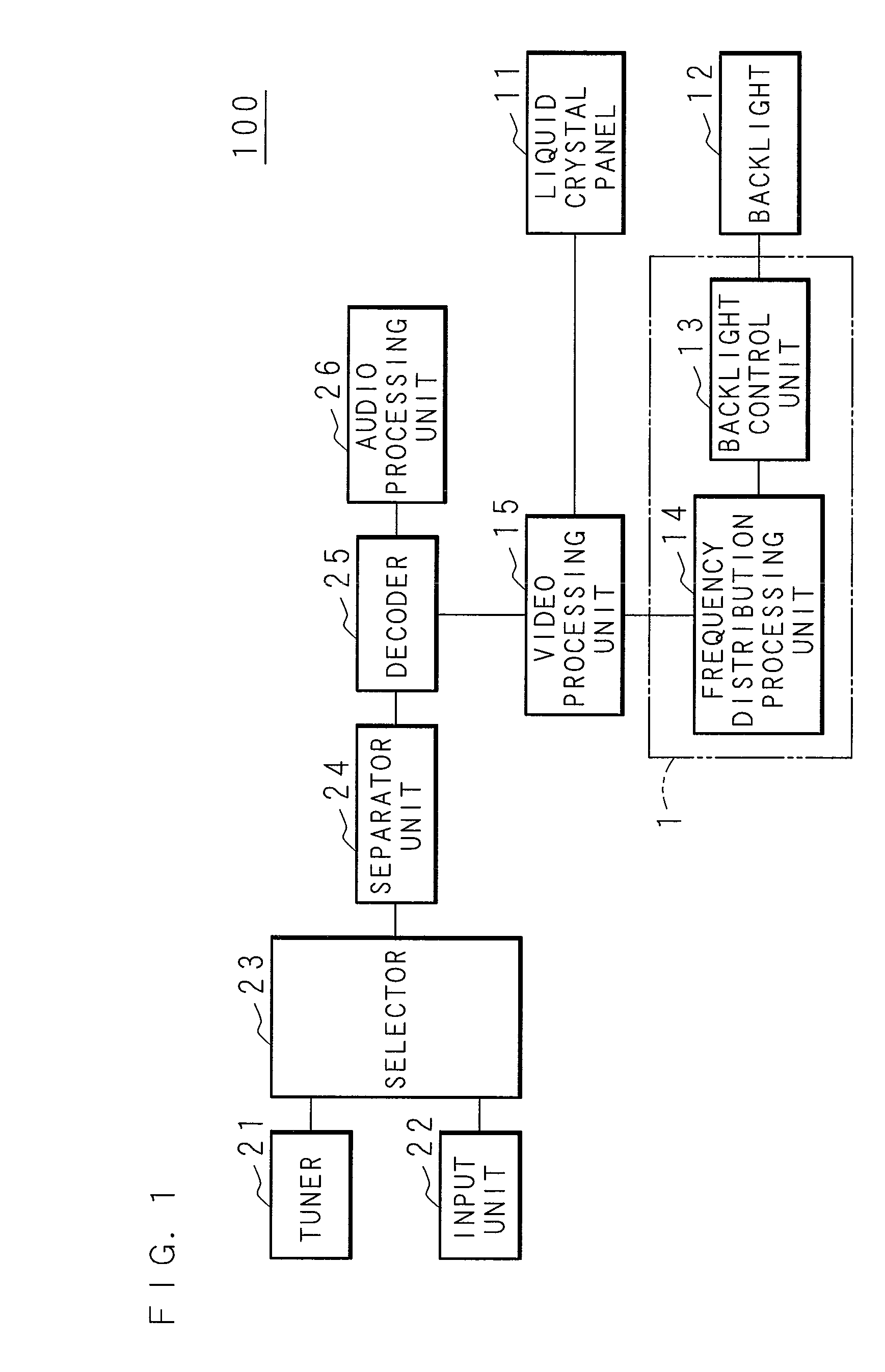
[0042]FIG. 1 is a block diagram showing the internal structure of a video display apparatus of Embodiment 1. A video display apparatus 100 of Embodiment 1 comprises a tuner 21, an input unit 22, a selector 23, a separator unit 24, a decoder 25, an audio processing unit 26, a video processing unit 15, a liquid crystal panel 11, a backlight 12, and a luminance control apparatus 1.

[0043]The tuner 21 receives broadcast waves with an antenna (not shown), and decodes the received broadcast waves into input data. The input unit 22 obtains input data inputted from an external device (not shown), such as a recorder device or a tuner device. The input data includes video data, audio data, and data for an electronic program guide (EPG), and the video display apparatus 100 of Embodiment 1 displays a video image based on the video data. The video display apparatus 100 can be configured to handle digital data, or analog data, as the input data.

[0044]The tuner 21 and the input unit 22 are connecte...

embodiment 2

[0061]In Embodiment 1, the lower limit of luminance is calculated according to the dark pixel ratio in a video image. However, if a high lower limit of luminance is set for a video image having low brightness on the whole, black floating occurs in the video image, and the quality of the video image is lowered. Embodiment 2 illustrates a mode in which the lower limit of luminance of the backlight 12 is calculated according to the brightness of the whole video image. Since the internal structure of the video display apparatus 100 according to Embodiment 2 is the same as that in Embodiment 1, the explanation thereof will be omitted.

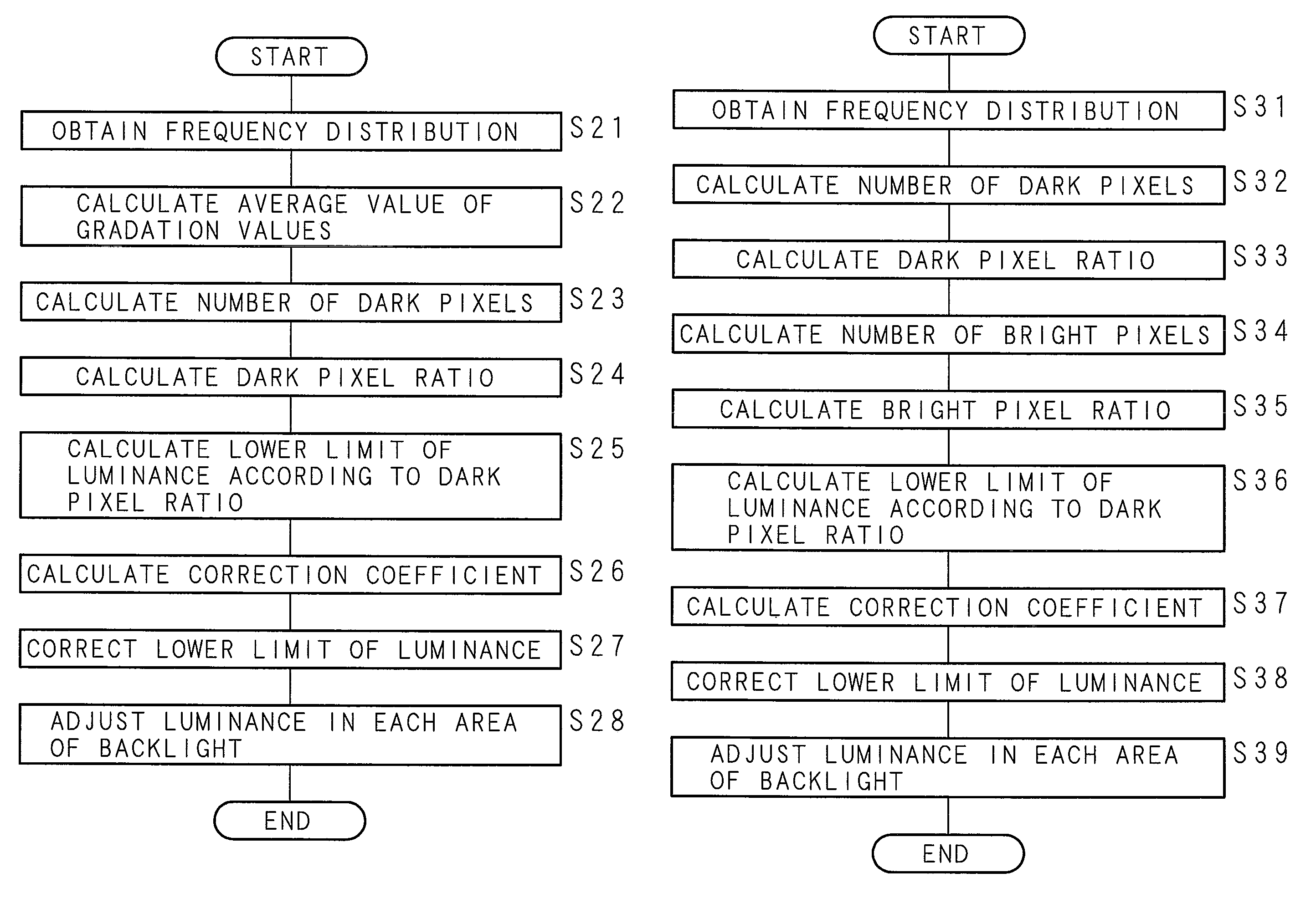
[0062]FIG. 7 is a flowchart showing the processing steps carried out by the video display apparatus 100 of Embodiment 2. The video processing unit 15 generates a video signal and outputs it to the frequency distribution processing unit 14. The frequency distribution processing unit 14 obtains the frequency distribution of gradation values of the respective p...

embodiment 3

[0069]In Embodiment 1, the lower limit of luminance in a plurality of areas of the backlight 12 is set smaller as the dark pixel ratio in the video image increases. By the way, among video images, there is a video image containing a large number of both of dark pixels and bright pixels, but not many pixels having intermediate gradation values. In Embodiment 1, when the dark pixel ratio in the video image is high, luminance blur tends to occur, and further when there are a large number of bright pixels in the video image, luminance blur is noticeable, and the quality of the video image is lowered. Embodiment 3 illustrates a mode in which the lower limit of luminance of the backlight 12 is calculated according to both the amount of dark pixels and the amount of bright pixels. Since the internal structure of the video display apparatus 100 according to Embodiment 3 is the same as that in Embodiment 1, the explanation thereof will be omitted.

[0070]FIG. 9 is a flowchart showing the proce...


PUM


Abstract

In a video display apparatus, a backlight for illuminating a liquid crystal panel is segmented into a plurality of areas. A frequency distribution processing unit calculates a dark pixel amount from the frequency distribution of the gradation values of pixels in a video image. A backlight control unit calculates a lower limit of luminance in each area included in the backlight so that the lower limit increases as the dark pixel amount becomes smaller. The backlight control unit adjusts the luminance in each area individually according to the gradation values in each portion of the video image, and adjusts the luminance in an area where the luminance is less than the lower limit to the lower limit. The difference in luminance between the areas illuminating dark portions of the video image is decreased, and the occurrence of luminance blur resulting from the difference in luminance between the areas is reduced.

Description

CROSS-REFERENCE TO RELATED APPLICATION[0001]This Non-provisional application claims priority under 35 U.S.C. §119(e) on U.S. Provisional Application No. 61 / 136,652 filed on Sep. 23, 2008, and under 35 U.S.C. §119(a) on Patent Application No. 2008-322694 filed in Japan on Dec. 18, 2008, the entire contents of which are hereby incorporated by reference.BACKGROUND[0002]1. Technical Field[0003]The present invention relates to a video display apparatus constructed using a liquid crystal panel and a backlight, and more specifically relates to a backlight luminance control apparatus which adjusts the quality of a video image by controlling the luminance distribution of the backlight and the video display apparatus.[0004]2. Description of Related Art[0005]Conventionally, liquid crystal displays are widely used as video display apparatuses, such as monitor devices for computers, and television receivers. A liquid crystal display is constructed using a liquid crystal panel and a backlight for...

Claims


Application Information

Patent Timeline
Patent Type & Authority Patents(United States)
IPC IPC(8): G09G3/36
CPCG09G3/3426G09G2320/0233G09G2320/0238G09G2320/0626G09G2330/021G09G2360/144G09G2360/16
Inventor KOIKE, AKIRATAKAKU, KOHICHIKOHNO, YOSHINORINAGASHIMA, SHINICHIYAGISAWA, HIDETOYAMADA, KODAI
Owner SHARP KK
Why Eureka
Try Eureka