System and method for increasing roadway width incorporating a reverse oriented retaining wall and soil nail supports

a reverse-oriented retaining wall and soil nail technology, applied in the direction of roads, roads maintainence, artificial islands, etc., can solve the problems of inability to widen the roadway, difficult roadway construction and maintenance, unstable earth surrounding or under a man-made structure, etc., and achieve the effect of increasing the roadway width

Active Publication Date: 2013-02-19
SOIL-NAIL HLDG LLC
View PDF141 Cites 6 Cited by
  • Summary
  • Abstract
  • Description
  • Claims
  • Application Information

AI Technical Summary

Benefits of technology

[0008]In accordance with the present invention, a system and method are provided for increasing roadway widths by incorporating reverse-oriented retaining walls and soil nail supports.
[0019]The reverse-oriented retaining wall of the present invention provides significant savings in terms of the amount of required backfill materials as well as construction materials, as compared to traditional construction designs. As one skilled in the art may appreciate, a prior art retaining wall is a vertical installation that commences at the surface of the adjacent sloping surface. In the case of extreme sloping surfaces or cliffs, a retaining wall may often have to be built hundreds of feet below the roadway. A large amount of backfill material is required since the backfill material must fill the entire gap between the retaining wall and the sloping surface. Gaining access to the location where the retaining wall may have to commence may be difficult for large vehicles, thereby increasing the difficulty of constructing the retaining wall. Obstructions may also require the retaining wall to be built a considerable lateral distance from the existing roadway which, increase overall cost and effort in using a retaining wall to widen the road.

Problems solved by technology

In some circumstances, the earth surrounding or under a man-made structure becomes unstable and therefore requires active supports, such as tie-backs, that are pre-tensioned subsurface installations used to restrain movement of the surrounding soil and rock.
Mountainous terrain provides a challenge for road designers to provide the required roadway width.
Two significant regulatory changes over recent years have made roadway construction and maintenance particularly challenging for mountainous areas.
Road widening efforts such as blasting or significant earth removal may not comply with environmental impact standards, thus preventing or greatly inhibiting the ability to widen a roadway.

Method used


Image

  • System and method for increasing roadway width incorporating a reverse oriented retaining wall and soil nail supports
  • System and method for increasing roadway width incorporating a reverse oriented retaining wall and soil nail supports
  • System and method for increasing roadway width incorporating a reverse oriented retaining wall and soil nail supports

Examples


Embodiment Construction

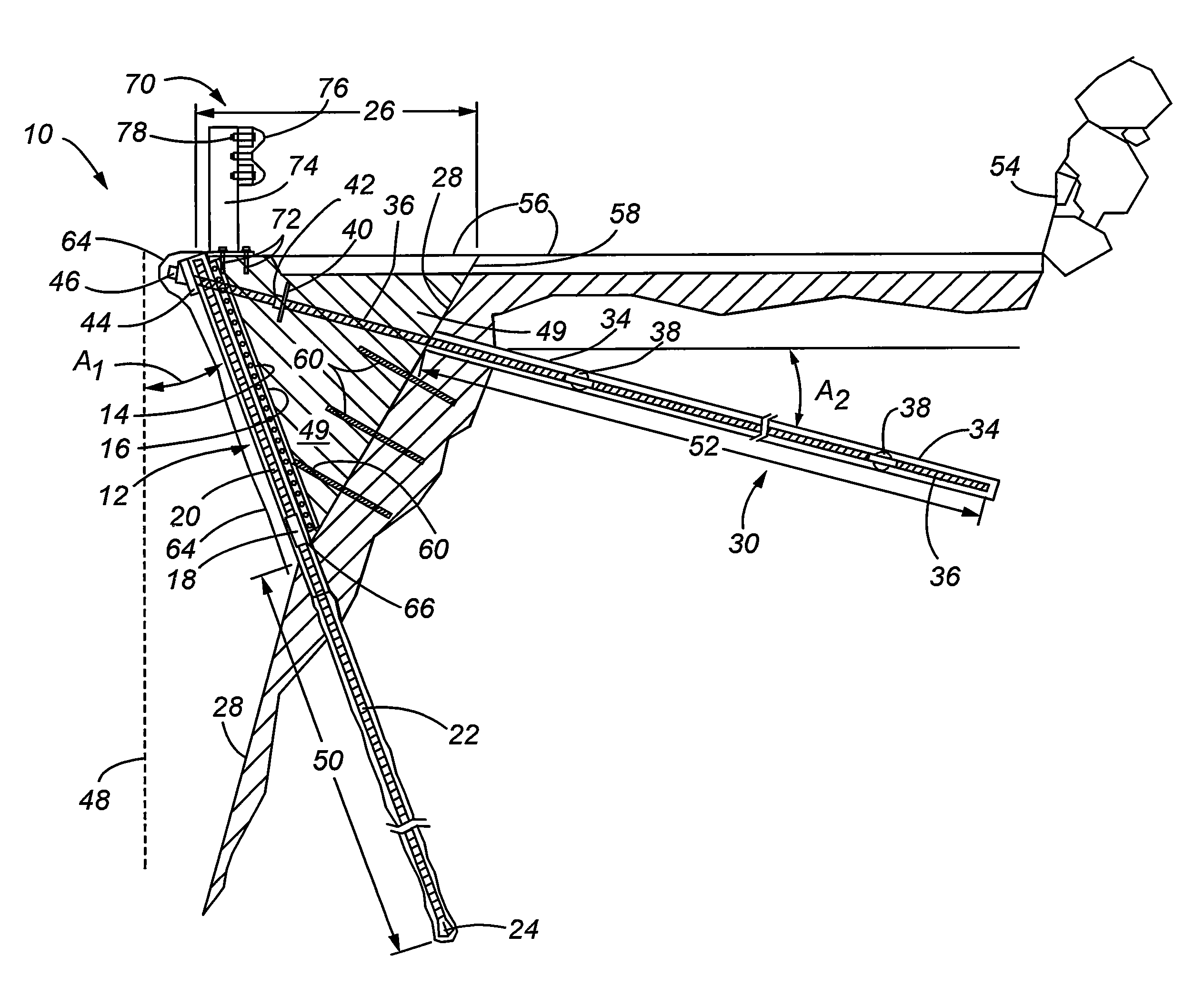
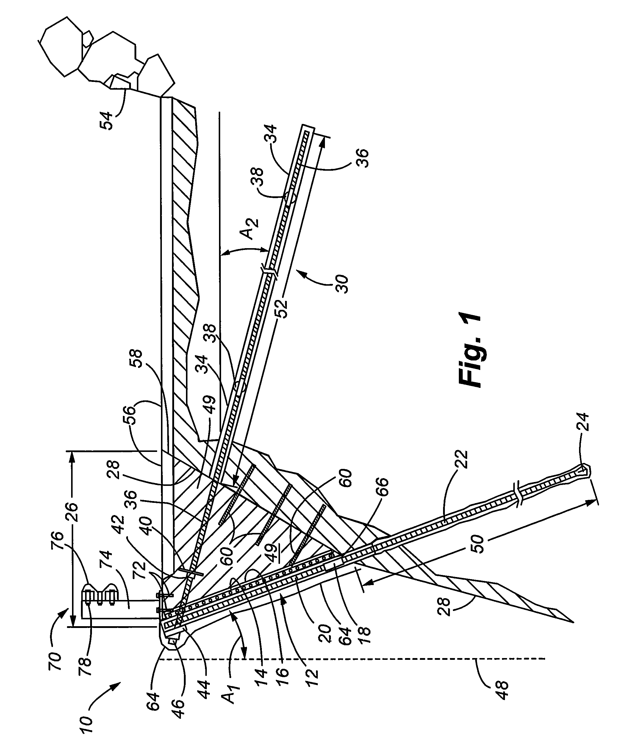
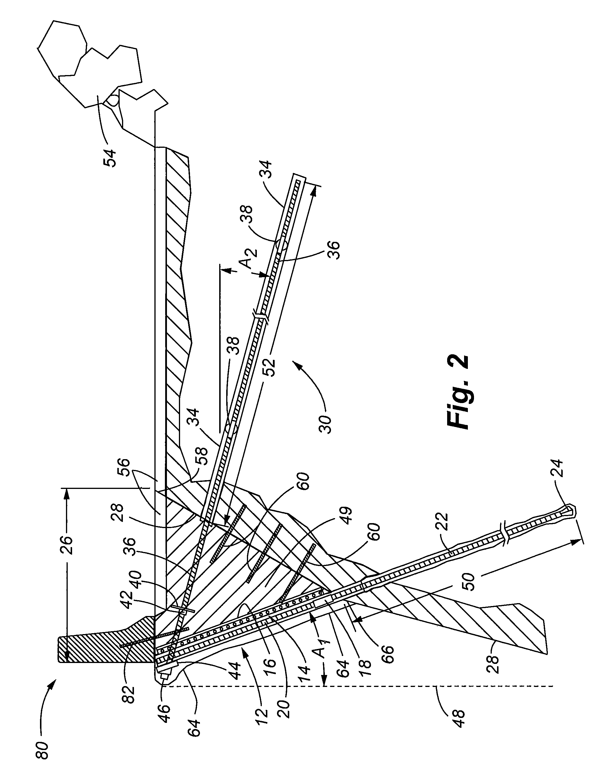
[0031]FIGS. 1 and 3 show the system of the invention in a first embodiment. The system includes a retaining wall 10 that is used to widen an existing roadway. A sloping surface 28 normally limits the width of the roadway on one lateral side of the road. The retaining wall components include a first set of soil nails 12 that are secured in the sloping surface 28. As best seen in FIG. 3, a plurality of the first set of nails 12 is spaced apart from one another along a length of the retaining wall 10. The angular extension of the soil nails 12 can be measured, for example, from a vertical angle A1. This angular extension generally defines the exterior face of the retaining wall as discussed further below. The first set of soil nails thereby form a first means for supporting the sloping surface.

[0032]Once the first set of nails 12 are installed, a wire mesh material 14 is placed over the exposed portions of the soil nails 12. The wire mesh is secured to the soil nails 12 using, for exam...


PUM


Abstract

A system and method are provided for increasing the width of an existing roadway. The system incorporates a reverse-oriented retaining wall and soil nail supports. The retaining wall is formed by a first set of soil nails, wire mesh material, and one or more geotextile material layers. An alternate embodiment forms the retaining wall with a plurality of concrete blocks stacked and spaced to form a block wall. The blocks are mounted over the first set of nails and can be filled with mortar. Backfill material fills a gap between the existing sloping surface and the retaining wall. A second set of soil nails can be provided for additional subsurface support. An upper surface of the backfill material can be paved to form the extended roadway width.

Description

FIELD OF THE INVENTION[0001]The present invention relates generally to systems and methods for constructing and repairing roadways, and more particularly, to a system and method for increasing the width of a roadway by incorporating a reverse-oriented retaining wall and subsurface soil nail supports.BACKGROUND OF THE INVENTION[0002]In the construction of buildings, bridges, and other man-made structures, it is well-known to place passive supports such as footers, piles, and other subsurface installations for supporting above ground structures. Subsurface supports can be generally classified in two types. Passive supports are those that require the earth around the subsurface support to first shift or move to mobilize the available tensile, bending, or shear capacities of the subsurface supports. Active supports are those that are pre-tensioned to prevent shifts in the earth.[0003]It is known to provide ground strengthening by driving, drilling, or launching elongate reinforcing memb...

Claims


Application Information

Patent Timeline
Patent Type & Authority Patents(United States)
IPC IPC(8): E02D17/20
CPCE01C1/00E01C3/00E02D5/76E02D17/20E02D17/207E02D29/0233E02D29/0208E02D29/0241E02D29/0291E02D17/18E02D29/02
Inventor BARRETT, ROBERT K.RUCKMAN, ALBERT C.RUCKMAN, TIMOTHY ALLENBARRETT, COLBYLOBATO, CAMERONBEARD, NATHAN
Owner SOIL-NAIL HLDG LLC
Why Eureka
Try Eureka