
Coaxial connector with enhanced shielding

a shielding and coaxial cable technology, applied in the direction of coupling device connection, coupling device details, coupling/disengagement of coupling parts, etc., can solve the problems of noise ingress in the cable distribution system, reduce the velocity or speed of signal propagation, and loosen the nut, etc., to achieve enhanced shielding, mechanical performance, and environmental performance.

Active Publication Date: 2013-02-19
HOLLAND ELECTRONICS
View PDF22 Cites 67 Cited by
  • Summary
  • Abstract
  • Description
  • Claims
  • Application Information

AI Technical Summary

Benefits of technology

[0011]An electrically conductive member interconnecting the front attachment nut and the connector body assures DC continuity and RF shielding to an F-Type male coaxial cable connector when the front attachment nut is loose. Unlike traditional loose nut shielding methods, embodiments of the present invention locate an electrical contact member between the connectors' attachment nut and a connector conductive body. Because RF currents travel mostly on a conductors' outer surface, the use of the connector body as a conductor offers, in various embodiments, one or more of enhanced shielding, mechanical performance, and environmental performance as compared to traditional designs. Moreover, in various embodiments, the present invention requires no spring or similar shielding member to electrically interconnect the attachment nut and either of the post and flange of the connector ferrule tube.

Problems solved by technology

With the increased use of internet / data applications on Cable TV systems, it has been found that outside electrical noise and signal ingress into the CATV network interferes with the data signals and reduces the velocity or speed of signal propagation.
One source of noise ingress in cable distribution systems is the coaxial cables' F-Type connector.
Despite attachment nut tightening specifications, such as 30 inch-pounds torque for some connectors, intended to insure a high degree of conductivity and radio frequency (“RF”) shielding, movement of the coaxial cable, variations in temperature, or poor initial installation workmanship can cause the F-Type male nut to loosen, allowing RF ingress through the RF gap created.
This method has had some success in resisting vibrational loosening, but it fails to prevent RF ingress if the nut is installed loose or later becomes loose.
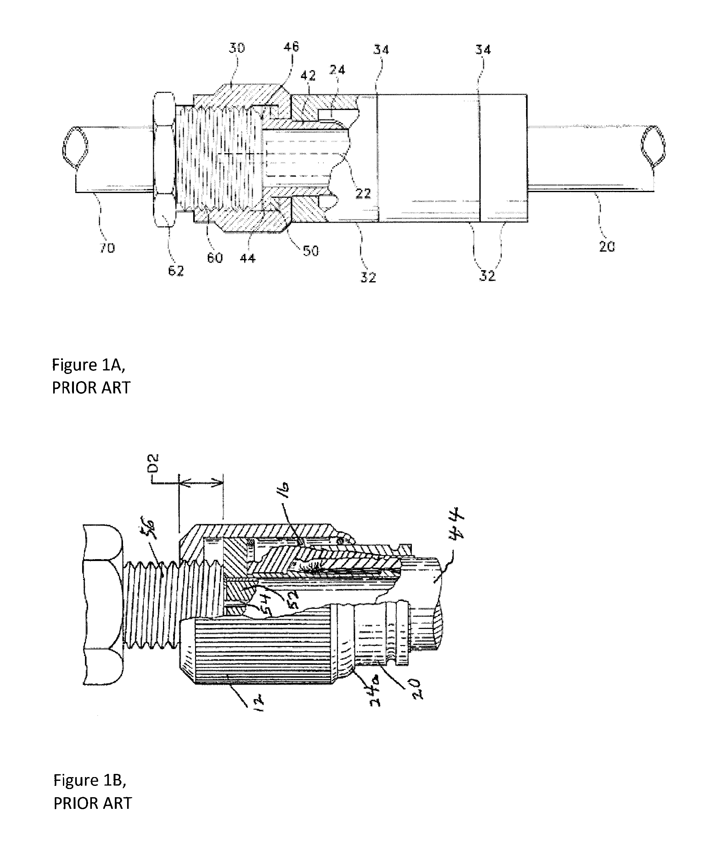
It is a disadvantage that this design requires a larger and more costly male connector nut assembly to house the spring.
It is a disadvantage that this design operates over only a short compression distance.
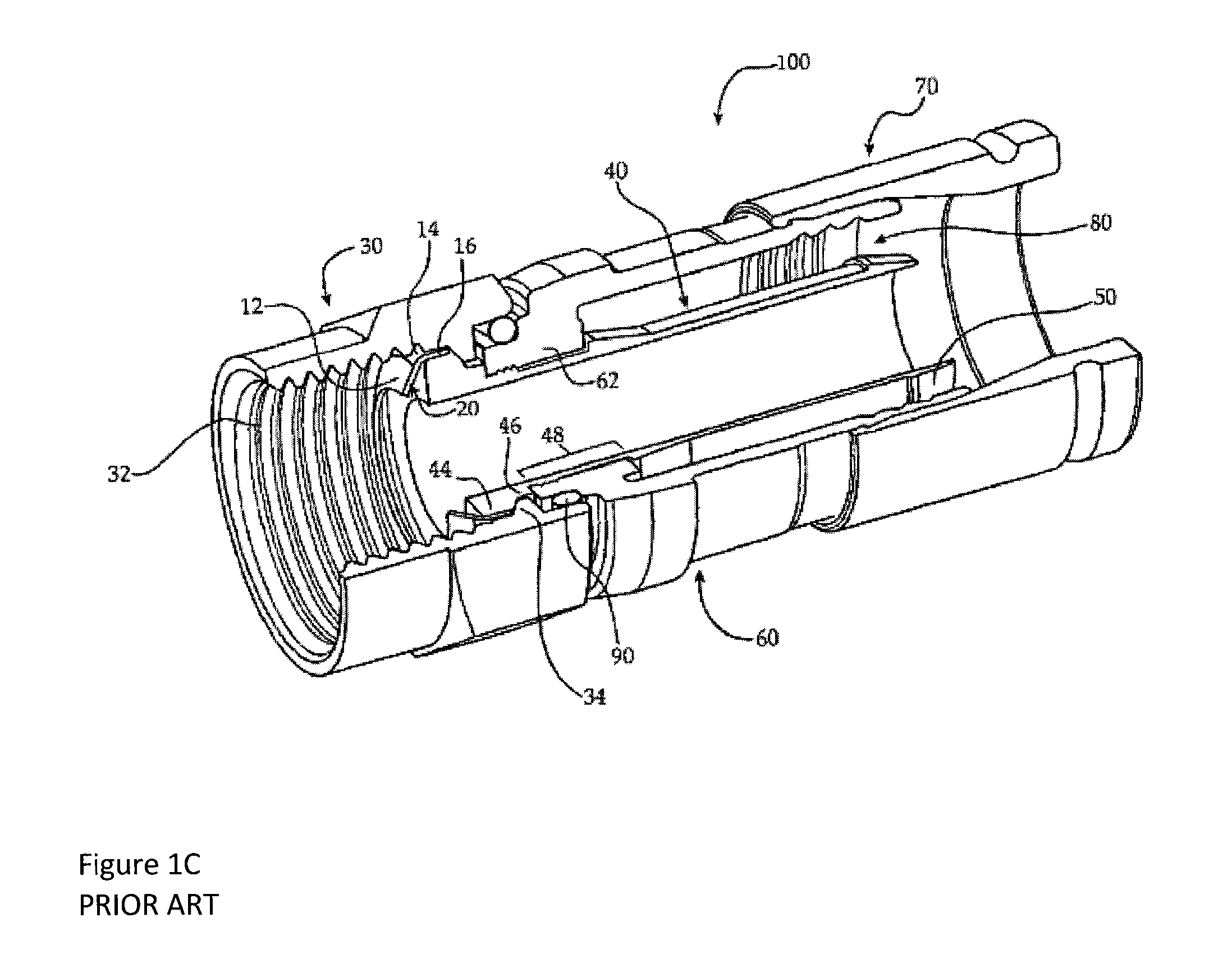
Disadvantages of this design include a large contact spring and grounding to an inner, smaller diameter ground plane.

Method used


Image

  • Coaxial connector with enhanced shielding
  • Coaxial connector with enhanced shielding
  • Coaxial connector with enhanced shielding

Examples


Embodiment Construction

[0021]The disclosure provided in the following pages describes examples of some embodiments of the invention. The designs, figures, and description are non-limiting examples of embodiments they disclose. For example, other embodiments of the disclosed device and / or method may or may not include the features described herein. Moreover, disclosed advantages and benefits may apply to only certain embodiments of the invention and should not be used to limit the disclosed invention.

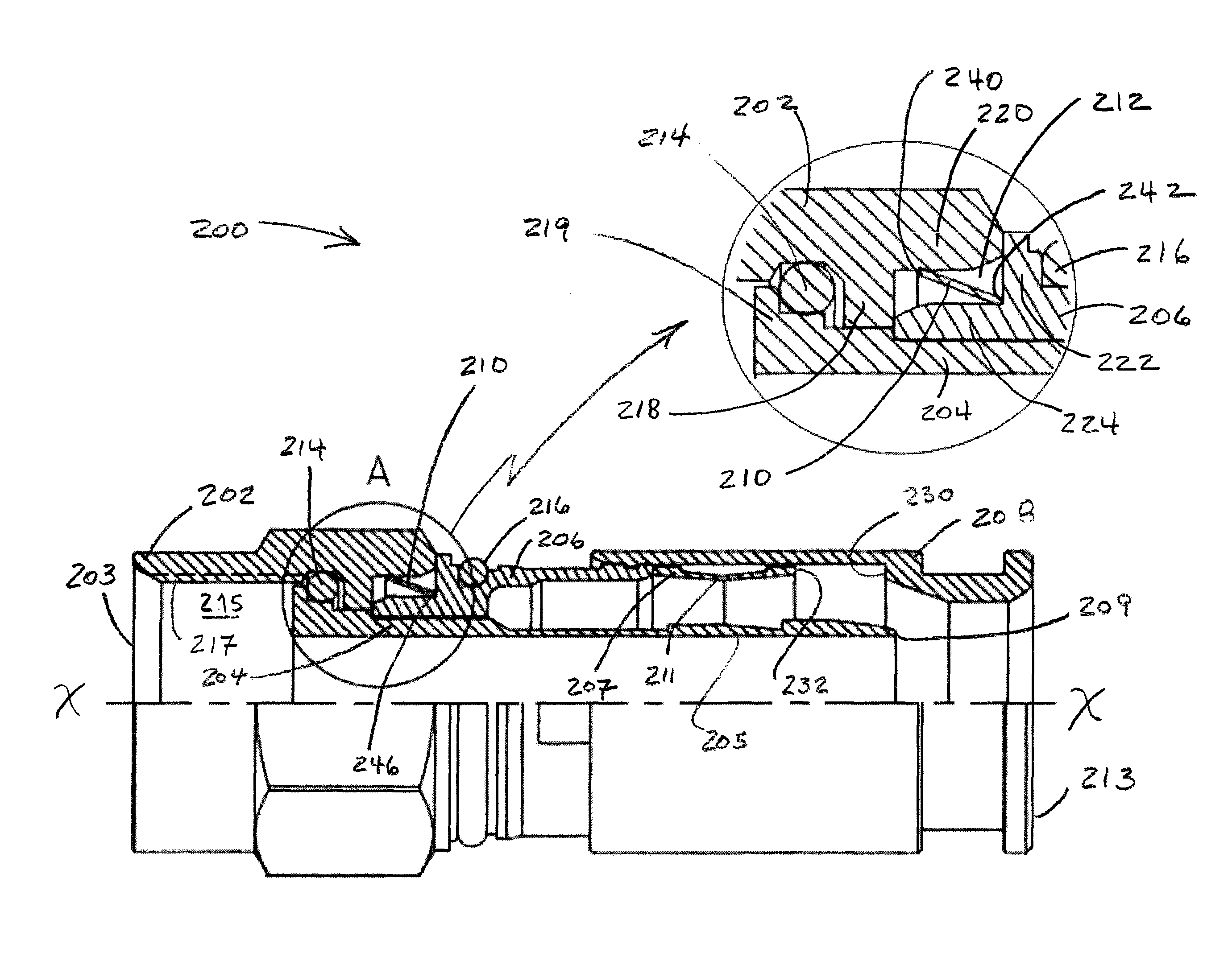
[0022]FIG. 2 shows a male F-Type coaxial cable connector in accordance with the present invention 200. The connector includes a post 204, a flange or flange-like structure 219 opposite a trailing end of the post 209, a rotatable front attachment nut surrounding the flange 202, and a connector body 206 affixed to the post adjacent to the nut. The nut end of the connector is referred to as the forward end 203 and the opposite end of the connector is referred to as the trailing end 213. A nut forward cavity 215 i...


PUM

PropertyMeasurementUnit
bridge angleaaaaaaaaaa
thicknessaaaaaaaaaa

Abstract

A male F-Type coaxial cable connector has an improved RF shield including a bridge located between and electrically interconnecting a connector fastening nut and a connector body portion.

Description

BACKGROUND OF THE INVENTION[0001]1. Field of the Invention[0002]The present invention relates to an article of manufacture for conducting electrical signals. In particular, a male F-Type coaxial cable connector includes a bridge enhancing the electromagnetic shielding provided by the mated connector.[0003]2. Discussion of the Related Art[0004]With the increased use of internet / data applications on Cable TV systems, it has been found that outside electrical noise and signal ingress into the CATV network interferes with the data signals and reduces the velocity or speed of signal propagation. Because shielding tends to reduce this undesirable interference, increasing the shielding of every component in the distribution system has become a goal of CATV system designs seeking improved data transmission performance.[0005]One source of noise ingress in cable distribution systems is the coaxial cables' F-Type connector. Male F-Type connectors generally include a post, a flange located at o...

Claims


Application Information

Patent Timeline
Patent Type & Authority Patents(United States)
IPC IPC(8): H01R9/05
CPCH01R13/622H01R13/6583H01R43/14H01R13/6581H01R9/0524Y10T29/49123Y10T29/49227H01R4/48
Inventor HOLLAND, MICHAELWEI, KAI-CHIH
Owner HOLLAND ELECTRONICS
Learn More